

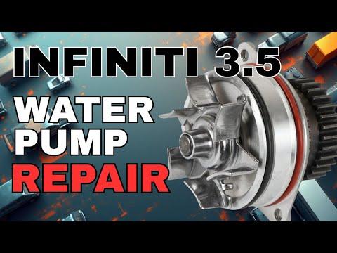
How to Replace the Water Pump on a 2013-2019 Nissan Pathfinder 3.5L V6 (Engine: V6 3.5L)
Advanced step-by-step guide with required tools, parts, torque specs, and timing-chain safety tips for 2013, 2014, 2015, 2016, 2017, 2018, 2019
How to Replace the Water Pump on a 2013-2019 Nissan Pathfinder 3.5L V6 (Engine: V6 3.5L)
Advanced step-by-step guide with required tools, parts, torque specs, and timing-chain safety tips for 2013, 2014, 2015, 2016, 2017, 2018, 2019


🔧 Pathfinder - Water Pump Replacement
Your Pathfinder uses an engine-driven water pump mounted behind the front timing-chain cover. The pump can be removed through its service opening, but the timing-chain tension must first be controlled precisely; an error can let the chain jump and cause serious engine damage.
Difficulty Level: Advanced | Estimated Time: 5-8 hours
Assumption: Your Pathfinder has its stock VQ35DD engine and factory accessory layout.
⚠️ Safety & Precautions
- ⚠️ Perform this repair only with the engine completely cold. Hot coolant can cause severe burns.
- 🛑 Do not rotate the crankshaft or camshafts after releasing timing-chain tension except exactly as directed.
- ⛓️ If the timing chain slips a tooth, stop immediately. The timing system must be exposed and correctly retimed before starting the engine.
- 🔩 Never rotate the crankshaft counterclockwise. Viewed from the pulley end, normal engine rotation is clockwise.
- 🚫 Do not use the camshaft sprockets or timing chain as leverage.
- 🏗️ Support your Pathfinder with jack stands. Never work underneath a vehicle held only by a floor jack.
- 🔋 Disconnect the negative battery terminal before working near the drive belt and engine wiring.
- 🐾 Coolant is poisonous. Keep it away from children and animals and take used coolant to an approved recycling facility.
- 📞 This is not a suitable first repair for a beginner. Professional service is strongly recommended unless you have prior timing-chain experience.
🔧 Required Tools
You'll need the following tools for this repair:
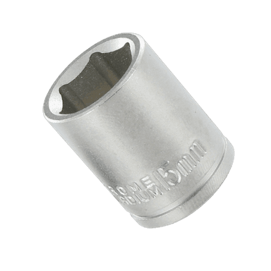
- 8mm socket
- 10mm socket
- 12mm socket
- 14mm socket
- 19mm socket
- 1/4-inch-drive ratchet
- 3/8-inch-drive ratchet
- 1/2-inch-drive breaker bar
- 3-inch socket extension
- 6-inch socket extension
- Torque wrench rated 5-30 Nm
- Torque wrench rated 20-150 Nm
- 6mm hex key
- M8 x 1.25mm extraction bolts, 50mm minimum length (specialty)
- Timing-chain tensioner retaining pin, 1.5mm diameter (specialty)
- Serpentine-belt tensioner tool (specialty)
- Hose-clamp pliers (specialty)
- Plastic trim-clip removal tool
- Plastic gasket scraper
- Spill-free coolant funnel (specialty)
- Drain pan rated 15-liter minimum
- Floor jack rated 2-ton minimum
- Jack stands rated 2-ton minimum
- Wheel chocks
- Inspection mirror
- LED work light
- Paint marker
- Shop towels
- Nitrile gloves
- Safety glasses
🔩 Required Parts
HowToo sells all the parts you need for this repair:
- Engine water pump - Qty: 1
- Water-pump O-ring seals - Qty: 2
- Water-pump service-cover O-ring - Qty: 1
- Nissan-compatible blue 50/50 premixed coolant - Qty: 2 gallons
- Accessory drive belt - Qty: 1 if worn or coolant-contaminated
Use the seals supplied for the VQ35DD pump. Do not substitute generic O-rings or mix Nissan blue coolant with an unknown coolant type.
📋 Before You Begin
- 📍 Park your Pathfinder on level ground, select Park, apply the parking brake, and let the engine cool overnight.
- 🛞 Place wheel chocks behind both rear wheels.
- 📱 No infotainment service mode, scan-tool command, or battery registration is required.
- 🗂️ Photograph the accessory-belt routing and every connector before disassembly.
- 🔋 Record any preferred audio settings, switch off the ignition, and disconnect the negative battery terminal.
- 🏗️ Raise the front with a floor jack and place it securely on jack stands at the designated front support points.
- 🔎 Inspect the pump area first. Coolant from the thermostat housing, hose connections, or front cover can imitate a leaking pump.
🔨 Step-by-Step Instructions
Follow these steps in order:
Step 1: Drain the Cooling System
- Put on nitrile gloves and safety glasses.
- Cover the radiator cap with a shop towel and remove it only after confirming the engine is completely cold.
- Place the 15-liter drain pan beneath the radiator drain.
- Open the plastic radiator drain valve by hand and allow the coolant to drain fully.
- Close the valve gently by hand after draining. Do not overtighten the plastic valve.
Step 2: Remove the Lower Covers and Right Front Wheel
- Use a plastic trim-clip removal tool to release the lower engine-cover clips.
- Use a 10mm socket and 3/8-inch-drive ratchet to remove the lower-cover bolts.
- Use a 19mm socket and 1/2-inch-drive breaker bar to loosen the right-front wheel nuts before lifting that corner.
- With your Pathfinder securely supported, use the 19mm socket and 3/8-inch-drive ratchet to remove the wheel.
- Use the plastic trim-clip removal tool and 10mm socket to remove the right-front inner splash shield.
Step 3: Remove the Air-Intake Duct
- Use a 10mm socket and 1/4-inch-drive ratchet to loosen the intake-duct clamp and remove its retaining fasteners.
- Disconnect any attached breather hose by releasing its clamp with hose-clamp pliers.
- Lift the duct away without pulling on wiring or plastic fittings.
- Label every disconnected hose and connector.
Step 4: Remove the Accessory Drive Belt
- Use a paint marker to draw an arrow showing the belt’s running direction if it will be reused.
- Fit the serpentine-belt tensioner tool to the automatic tensioner and rotate it slowly to release belt tension.
- Slide the belt from one accessible pulley, then slowly release the tensioner.
- Remove the belt and inspect it for cracks, glazing, or coolant contamination.
Step 5: Gain Access to the Water-Pump Service Cover
- Use the 10mm, 12mm, and 14mm sockets with the appropriate ratchet and extensions to remove only the brackets and wiring retainers obstructing the water-pump service cover.
- Move wiring aside without stretching it. Do not disconnect fuel-system components.
- Use the inspection mirror and LED work light to identify the small water-pump service cover in the front timing-chain cover.
- Keep every bolt organized by its original location because lengths can differ.
Step 6: Position and Mark the Timing System
- Install a 19mm socket and 1/2-inch-drive breaker bar on the crankshaft pulley bolt.
- Rotate the crankshaft clockwise only until the factory timing reference marks align at the specified compression position.
- Use a paint marker to place matching reference marks across the visible chain and sprocket positions.
- Do not use the paint marks as a substitute for factory timing marks.
- If the factory marks cannot be positively identified, stop and obtain the VQ35DD timing procedure before continuing.
Step 7: Remove the Chain-Tensioner Access Cover
- Use a 10mm socket, 1/4-inch-drive ratchet, and 3-inch extension to remove the chain-tensioner access-cover bolts.
- Remove the cover and its O-ring carefully.
- Use the LED work light and inspection mirror to locate the timing-chain tensioner plunger and retaining hole.
- The tensioner is a spring-and-oil-loaded device that keeps the timing chain tight.
Step 8: Retract and Lock the Timing-Chain Tensioner
- Use a 6mm hex key only if needed to control the tensioner mechanism while gently pressing the plunger inward.
- Insert the 1.5mm timing-chain tensioner retaining pin fully through the aligned holes to lock the plunger in its compressed position.
- Confirm the pin is secure before releasing pressure.
- Do not continue if the tensioner cannot be fully locked or if the chain becomes loose enough to leave a sprocket tooth.
- One slipped tooth can damage the engine.
Step 9: Remove the Water-Pump Service Cover
- Use a 10mm socket, 1/4-inch-drive ratchet, and 3-inch extension to remove the water-pump service-cover bolts.
- Remove the cover carefully without dropping debris into the timing-chain cavity.
- Remove and discard the old service-cover O-ring.
- Use a plastic gasket scraper and shop towels to clean the cover’s sealing groove.
Step 10: Remove the Water Pump
- Use a 10mm socket and 1/4-inch-drive ratchet to remove the water-pump retaining bolts evenly.
- Thread the two M8 x 1.25mm extraction bolts into the pump’s threaded removal holes by hand.
- Use a 12mm socket and 1/4-inch-drive ratchet to turn the extraction bolts alternately, no more than one turn at a time.
- Keep the pump straight as the bolts press it out of the engine.
- Do not pry between the aluminum sealing surfaces.
- Withdraw the pump carefully while keeping the timing chain engaged with its sprockets.
Step 11: Clean and Inspect the Pump Bore
- Use a plastic gasket scraper and shop towels to remove residue from the pump bore.
- Do not allow coolant, dirt, or pieces of old seal to fall into the timing-chain cavity.
- Inspect the bore for corrosion, scratches, and damaged sealing surfaces using the LED work light.
- Inspect the visible chain guides for cracks or abnormal wear. Stop if any guide is damaged.
Step 12: Install the New Water Pump
- Install both new water-pump O-rings in their correct grooves by hand.
- Wet the O-rings lightly with fresh Nissan-compatible blue coolant. Do not use RTV sealant.
- Guide the pump squarely into its bore while keeping its sprocket correctly engaged with the timing chain.
- Press the pump inward evenly by hand. Never pull it into position with the bolts if the O-rings bind.
- Start all retaining bolts by hand.
- Use a 10mm socket and the 5-30 Nm torque wrench to tighten the water-pump bolts evenly to Torque to 9.8 Nm (87 in-lbs).
Step 13: Restore Timing-Chain Tension
- Check that the timing chain remains fully seated and that all factory and paint reference marks remain aligned.
- Support the tensioner plunger with the 6mm hex key if required, then remove the 1.5mm retaining pin.
- Allow the plunger to extend slowly against the chain guide.
- Use the 19mm socket and 1/2-inch-drive breaker bar to rotate the crankshaft clockwise by hand through two complete revolutions.
- Stop immediately if the crankshaft binds. Do not use the starter motor to force rotation.
- Return to the timing reference position and confirm the factory timing relationship. Painted chain links may not realign after two revolutions.
Step 14: Install the Service Covers
- Fit a new O-ring to the water-pump service cover and wet it lightly with fresh coolant.
- Position the cover and start every bolt by hand.
- Use a 10mm socket and 5-30 Nm torque wrench to tighten the water-pump service-cover bolts to Torque to 9.8 Nm (87 in-lbs).
- Reinstall the chain-tensioner access cover with its serviceable seal.
- Use a 10mm socket and 5-30 Nm torque wrench to tighten the tensioner access-cover bolts to Torque to 9.8 Nm (87 in-lbs).
Step 15: Reassemble the Engine Compartment
- Reinstall the removed brackets and wiring retainers using the 10mm, 12mm, and 14mm sockets with the appropriate ratchet.
- Return every bolt to its original location and tighten bracket fasteners securely without overtightening aluminum threads.
- Reconnect any intake breather hose using hose-clamp pliers.
- Reinstall the air-intake duct and tighten its clamp with a 10mm socket and 1/4-inch-drive ratchet.
Step 16: Reinstall the Accessory Drive Belt
- Route the belt according to the photograph taken before removal.
- Use the serpentine-belt tensioner tool to rotate the automatic tensioner.
- Slip the belt over the final pulley, then release the tensioner slowly.
- Verify every belt rib is seated correctly in every grooved pulley.
Step 17: Refill and Bleed the Cooling System
- Install the spill-free coolant funnel at the radiator filler neck.
- Slowly add Nissan-compatible blue 50/50 premixed coolant until the radiator remains full.
- Fill the coolant reservoir to the MAX line.
- Reconnect the negative battery terminal with a 10mm socket and 1/4-inch-drive ratchet.
- Set the cabin temperature to maximum heat and the blower to low.
- Start the engine and let it idle while watching the temperature gauge, coolant level, and pump area.
- Add coolant as trapped air leaves the system. Continue until the heater stays hot and bubbles stop.
- Shut the engine off immediately if the temperature rises above normal, the heater turns cold, or abnormal chain noise is heard.
- Let the engine cool completely before removing the funnel and installing the radiator cap.
Step 18: Reinstall the Splash Shield and Wheel
- Use the plastic trim-clip removal tool and 10mm socket to reinstall the right-front splash shield and lower engine cover.
- Install the wheel and start all wheel nuts by hand.
- Use the floor jack to raise your Pathfinder, remove the jack stands, and lower it to the ground.
- Use a 19mm socket and 20-150 Nm torque wrench to tighten the wheel nuts in a star pattern to Torque to 113 Nm (83 ft-lbs).
✅ After Repair
- 🔍 Check the water-pump service cover, radiator drain, and disturbed hose connections for leaks.
- 👂 Listen for rattling, scraping, or whining from the timing-cover area. Shut off the engine immediately if abnormal noise is present.
- 🌡️ Take a short test drive while monitoring the temperature gauge. It must remain in its normal range.
- 🔥 Confirm the cabin heater produces steady heat at idle and while driving.
- ❄️ Let the engine cool completely, then recheck the radiator and reservoir levels.
- 🧪 Reinspect for leaks after the test drive and again the following morning.
- 🛑 If a timing-related fault, misfire, overheating condition, or abnormal noise appears, do not continue driving.
💰 DIY vs Shop Cost
Shop Cost: ₹45,000-₹90,000 (parts + labor)
DIY Cost: ₹10,000-₹25,000 (parts only)
You Save: ₹35,000-₹65,000 by doing it yourself!
Labor rates and imported-parts availability around Sonīpat vary considerably. This repair takes a shop approximately 5-8 hours.
🎯 Ready to get started?
HowToo makes it easy: same-day/2-day shipping on every part, plus all the tools and specialty tools you need! Check out the parts and tools sections below to add everything to your cart.