

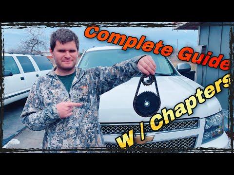
How to Replace the Timing Chain on a 2015-2018 Chevrolet Tahoe 5.3L V8 (Trim: LT | Engine: V8 5.3L)
Advanced step-by-step guide with required tools, parts, torque specs, and safety tips for 2015, 2016, 2017, 2018
How to Replace the Timing Chain on a 2015-2018 Chevrolet Tahoe 5.3L V8 (Trim: LT | Engine: V8 5.3L)
Advanced step-by-step guide with required tools, parts, torque specs, and safety tips for 2015, 2016, 2017, 2018


🔧 Tahoe - Timing Chain Replacement
Your Tahoe’s 5.3L V8 does not use a timing belt. It uses an internal timing chain that normally requires replacement only when confirmed worn, damaged, or responsible for timing-related fault codes.
This is a major engine repair involving the cooling system, oil pan seal, crankshaft pulley, and valve timing. Incorrect timing can cause severe engine damage.
Difficulty Level: Advanced | Estimated Time: 12-18 hours
Assumption: These instructions cover the stock 5.3L L83 engine; four-wheel-drive models require additional front differential clearance work.
⚠️ Safety & Precautions
- ⚠️ Disconnect the negative battery cable before beginning.
- ⚠️ Allow the engine to become completely cold before draining coolant.
- ⚠️ Support your Tahoe with correctly rated jack stands. Never work beneath a vehicle supported only by a jack.
- ⚠️ Do not rotate the crankshaft or camshaft independently after removing the chain.
- ⚠️ Variable valve timing components must remain clean. Dirt can block their small oil passages.
- ⚠️ The crankshaft balancer bolt is torque-to-yield and must be replaced.
- ⚠️ Air-conditioning lines are moved only as allowed by their flexible sections. Do not open the refrigerant system.
- ⚠️ On four-wheel-drive models, support the front differential before removing its fasteners.
🔧 Required Tools
You'll need the following tools for this repair:
- Metric socket set (7mm-24mm)
- Metric wrench set (8mm-21mm)
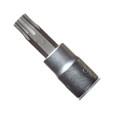
- Torx socket set (T20-T50)
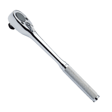
- 3/8-inch drive ratchet
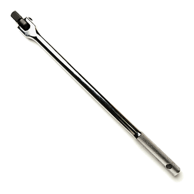
- 1/2-inch drive breaker bar (24-inch minimum)
- 1/2-inch drive torque wrench (30-250 ft-lbs)
- 3/8-inch drive torque wrench (5-80 ft-lbs)
- Torque-angle gauge (specialty)
- Crankshaft balancer puller (specialty)
- Crankshaft balancer installer (specialty)
- Flywheel holding tool (specialty)
- Camshaft actuator holding tool (specialty)
- Serpentine-belt tensioner tool (specialty)
- Plastic gasket scraper
- Plastic trim-clip removal tool
- Two-jaw hose-clamp pliers
- Needle-nose pliers
- Flat-blade screwdriver
- Engine support fixture (1,000-lb minimum)
- Hydraulic floor jack (rated 3-ton minimum)
- Jack stands (rated 3-ton minimum)
- Wheel chocks
- Drain pan (15-quart minimum)
- Fluid funnel
- Engine assembly lubricant
- Brake-cleaner aerosol
- Lint-free shop towels
- Paint marker
- Nitrile gloves
- Safety glasses
🔩 Required Parts
HowToo sells all the parts you need for this repair:
- Timing chain - Qty: 1
- Camshaft position actuator and sprocket assembly - Qty: 1 if worn or faulted
- Crankshaft timing sprocket - Qty: 1 if worn
- Timing chain tensioner - Qty: 1
- Timing chain guide - Qty: 1 set
- Front engine cover gasket set - Qty: 1
- Front crankshaft oil seal - Qty: 1
- Water pump gaskets - Qty: 2
- Crankshaft balancer bolt - Qty: 1
- Camshaft actuator bolt - Qty: 1
- Oil-pump pickup tube O-ring - Qty: 1 if disturbed
- Oil pan gasket - Qty: 1 if the oil pan is removed
- GM-approved RTV engine sealant - Qty: 1 tube
- Dex-Cool-compatible coolant concentrate - Qty: 2 gallons
- Distilled water - Qty: 2 gallons
- SAE 0W-20 dexos1-approved engine oil - Qty: 8 quarts
- Engine oil filter - Qty: 1
📋 Before You Begin
- 📋 Park on level ground, select Park, apply the parking brake, and chock the rear wheels.
- 📋 Record radio presets and other personalized settings.
- 📋 Turn the ignition off and keep the key or transmitter away from your Tahoe.
- 📋 Disconnect the negative battery terminal with a 10mm socket.
- 📋 Obtain the engine’s current GM service-information torque table before assembly. GM uses several torque-plus-angle fasteners, and values can vary by component revision.
- 📋 Diagnose the problem before disassembly. A worn timing chain should be supported by fault codes, excessive crank-to-cam variation, abnormal chain noise, or physical inspection.
🔨 Step-by-Step Instructions
Follow these steps in order:
Step 1: Disconnect Power and Raise the Vehicle
- Use a 10mm socket to disconnect the negative battery cable.
- Use a 3-ton floor jack at the specified front lifting point, then place 3-ton jack stands under the frame support points.
- Remove the lower splash shield with the appropriate 7mm, 10mm, and 15mm sockets.
Step 2: Drain the Cooling System and Engine Oil
- Place a 15-quart drain pan below the radiator drain and open it carefully with pliers.
- Remove the coolant reservoir cap only when the engine is cold.
- Use a 15mm socket to remove the engine-oil drain plug and drain the oil.
- Reinstall the drain plug with a torque wrench to Torque to 25 Nm (18 ft-lbs).
- Remove the oil filter by hand or with an appropriate filter wrench.
Step 3: Remove the Intake Duct and Cooling Fan Assembly
- Use a flat-blade screwdriver or 8mm socket to loosen the intake-duct clamps.
- Disconnect the airflow sensor connector and remove the intake duct.
- Use a plastic trim-clip tool and appropriate sockets to remove the upper radiator cover and fan shroud fasteners.
- Disconnect the electric fan connectors, then lift the fan and shroud assembly out together.
- Label every connector before unplugging it.
Step 4: Remove the Drive Belt and Front Accessories
- Photograph the belt routing before removal.
- Use a serpentine-belt tensioner tool to rotate the tensioner and remove the belt.
- Use the metric socket set to unbolt the alternator and move it aside.
- Use the metric socket set to unbolt the power-steering and air-conditioning brackets as necessary.
- Do not disconnect the air-conditioning refrigerant hoses.
- Use hose-clamp pliers to disconnect the accessible coolant hoses.
Step 5: Remove the Water Pump
- Disconnect the water-pump hoses with hose-clamp pliers.
- Use a 15mm socket to remove the water-pump bolts.
- Remove the water pump and both gaskets.
- During assembly, tighten the water-pump bolts evenly with a torque wrench to Torque to 30 Nm (22 ft-lbs).
Step 6: Remove the Crankshaft Balancer
- Install a flywheel holding tool to prevent the crankshaft from rotating. A flywheel holding tool locks the engine’s flywheel while loosening tight fasteners.
- Use a 1/2-inch breaker bar and the correct metric socket to remove the crankshaft balancer bolt.
- Use a crankshaft balancer puller to remove the balancer. Do not use a jaw puller against the outer ring.
- Inspect the balancer’s rubber isolator and sealing surface. Replace the balancer if cracked, shifted, or grooved.
Step 7: Create Oil-Pan Clearance
- Support the engine with a 1,000-lb engine support fixture.
- Use the metric socket set to loosen or remove the oil pan fasteners required to separate the oil pan from the front cover.
- On four-wheel-drive models, support the front differential with a 3-ton floor jack and remove the differential mounting hardware needed for oil-pan clearance.
- Do not let the front differential hang from its axle shafts or wiring.
- Front-cover removal requires an unbroken oil-pan seal.
Step 8: Remove the Front Engine Cover
- Disconnect the camshaft actuator, crankshaft sensor, and nearby harness retainers by hand and with a plastic trim tool.
- Use the metric socket set to remove every front-cover bolt, noting each bolt’s location and length.
- Carefully separate the cover using a plastic gasket scraper. Do not drive a metal screwdriver between the aluminum sealing surfaces.
- Remove and discard the old front crankshaft seal and cover gaskets.
Step 9: Set the Engine to the Timing Position
- Temporarily install the old crankshaft bolt and turn it clockwise with a breaker bar.
- Align the crankshaft sprocket timing mark with the camshaft actuator timing mark in the factory-specified position.
- Use a paint marker to duplicate the timing-mark relationship before removing the chain.
- Do not rotate the crankshaft backward to reach the marks.
Step 10: Remove the Timing Chain Components
- Install the camshaft actuator holding tool. This tool keeps the variable valve timing sprocket from turning unexpectedly.
- Use the appropriate metric socket and breaker bar to remove the camshaft actuator bolt.
- Use the metric socket set to remove the tensioner and chain guide.
- Remove the camshaft actuator, timing chain, and crankshaft sprocket as an assembly where possible.
- Inspect the oil-pump drive components, sprocket teeth, chain guides, tensioner, and actuator for scoring or debris.
Step 11: Install the New Timing Set
- Lubricate the chain, sprockets, and guide surfaces with clean 0W-20 engine oil or engine assembly lubricant.
- Align the timing marks exactly and install the crankshaft sprocket, chain, and camshaft actuator.
- Install the new guide and tensioner with the metric socket set.
- Release the tensioner only after all timing marks are aligned.
- Install a new camshaft actuator bolt and tighten it using the current GM service-information torque-plus-angle specification for the replacement actuator.
- Do not reuse the old actuator bolt.
- Recheck all timing marks before rotating anything.
Step 12: Verify Mechanical Timing
- Remove the holding tools.
- Use the old crankshaft bolt and breaker bar to rotate the crankshaft clockwise through two complete revolutions.
- Stop immediately if the engine binds. Do not force it.
- Return the crankshaft to the timing position and verify the sprocket marks align correctly.
- The marked chain links may not return to their original positions after rotation; verify the sprocket marks instead.
Step 13: Reseal and Install the Front Cover
- Use a plastic gasket scraper, brake cleaner, and lint-free towels to clean the front-cover, block, and oil-pan sealing surfaces.
- Install new front-cover gaskets and a new crankshaft seal.
- Apply GM-approved RTV sealant at the block-to-oil-pan and block-to-cylinder-head joints.
- Install the cover while the sealant remains workable.
- Use the metric socket set and torque wrenches to tighten the front-cover bolts in the factory sequence and by bolt size.
- Use the crankshaft balancer installer to center the lower cover and seal around the crankshaft before final tightening.
Step 14: Reseal the Oil Pan
- Apply GM-approved RTV sealant at the front-cover junctions.
- Raise the oil pan evenly and install its bolts by hand.
- Use the metric socket set and torque wrench to tighten the oil-pan fasteners in the factory sequence.
- Reinstall the front differential on four-wheel-drive models using its specified mounting sequence and verified GM torque values.
Step 15: Install the Crankshaft Balancer
- Lubricate the balancer hub lightly with clean engine oil.
- Use the crankshaft balancer installer to press the balancer fully onto the crankshaft.
- Never pull the balancer into place using the new bolt.
- Install the flywheel holding tool, then install a new crankshaft balancer bolt.
- Use the 1/2-inch torque wrench and torque-angle gauge to complete the exact GM torque-plus-angle procedure supplied for the new bolt.
- Do not reuse the old crankshaft balancer bolt.
Step 16: Reassemble the Front Accessories
- Install the water pump with new gaskets using a 15mm socket.
- Tighten the water-pump bolts evenly to Torque to 30 Nm (22 ft-lbs).
- Reinstall all accessory brackets with the metric socket set and tighten them to their component-specific GM specifications.
- Reconnect the coolant hoses with hose-clamp pliers.
- Install the drive belt with the serpentine-belt tensioner tool, following the original routing.
- Reinstall the fan assembly, shrouds, intake duct, sensor connector, and lower splash shield.
Step 17: Refill Fluids and Reconnect the Battery
- Install a new oil filter by hand until its gasket contacts the base, then tighten it an additional three-quarters turn.
- Use a funnel to add the specified 0W-20 dexos1-approved engine oil. Verify the final level with the dipstick rather than relying only on stated capacity.
- Use a funnel to fill the cooling system with a 50/50 mixture of Dex-Cool-compatible coolant and distilled water.
- Use a 10mm socket to reconnect the negative battery cable.
✅ After Repair
- ✅ Disable fuel delivery and crank the engine in several short cycles to build oil pressure before the first start.
- ✅ Restore fuel delivery, start the engine, and shut it off immediately if oil pressure does not rise or abnormal mechanical noise is heard.
- ✅ Inspect the front cover, crankshaft seal, oil pan, water pump, drain plug, and filter for leaks.
- ✅ Allow the engine to reach operating temperature while monitoring coolant temperature.
- ✅ Let the engine cool completely, then recheck the coolant and engine-oil levels.
- ✅ Use a compatible scan tool to clear stored fault codes and perform a crankshaft-position variation relearn if commanded by the diagnostic procedure.
- ✅ Road-test your Tahoe gently, then perform a final leak and fluid-level inspection.
💰 DIY vs Shop Cost
Shop Cost: ₹180,000-₹350,000 (parts + labor)
DIY Cost: ₹45,000-₹110,000 (parts only)
You Save: ₹135,000-₹240,000 by doing it yourself!
Imported parts and specialist labor vary significantly in Haryana. This repair takes a shop approximately 12-16 hours, with additional time possible on four-wheel-drive models.
🎯 Ready to get started?
HowToo makes it easy: same-day/2-day shipping on every part, plus all the tools and specialty tools you need! Check out the parts and tools sections below to add everything to your cart.