

How to Replace the MAF Sensor on a 2012-2020 Chevrolet Impala 3.6L (Trim: LT | Engine: V6 3.6L)
Step-by-step instructions with required tools, torque specs, safety tips, and code clearing for 2012, 2013, 2015, 2016, 2017, 2018, 2019
How to Replace the MAF Sensor on a 2012-2020 Chevrolet Impala 3.6L (Trim: LT | Engine: V6 3.6L)
Step-by-step instructions with required tools, torque specs, safety tips, and code clearing for 2012, 2013, 2015, 2016, 2017, 2018, 2019


🔧 Impala - Mass Air Flow Sensor Replacement
The mass air flow (MAF) sensor measures how much air enters your Impala’s 3.6L engine. Replacing a faulty sensor can correct rough running, poor acceleration, reduced fuel economy, and MAF-related check-engine codes.
Difficulty Level: Beginner | Estimated Time: 20-30 minutes
⚠️ Safety & Precautions
- ⚠️ Switch the ignition off and keep the key away from the vehicle.
- 🧊 Let the engine cool before working near the intake and exhaust components.
- 🚫 Never touch the sensing elements inside the new MAF sensor.
- 💧 Do not apply oil, cleaner, grease, or sealant to the sensor.
- 🔋 Battery disconnection is not required for this repair.
🔧 Required Tools
You'll need the following tools for this repair:
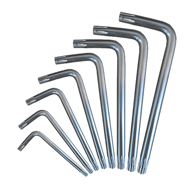
- Torx T20 screwdriver
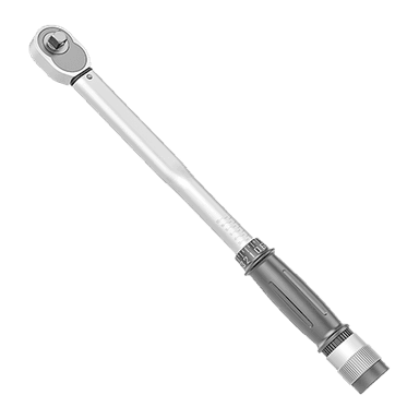
- 1/4-inch drive inch-pound torque wrench
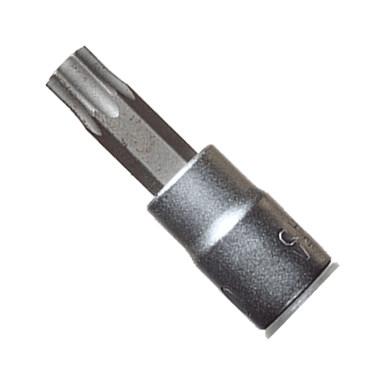
- 1/4-inch drive Torx T20 bit socket
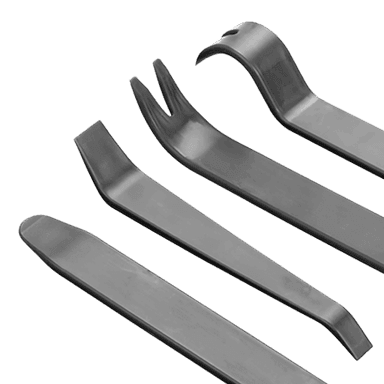
- Plastic trim tool
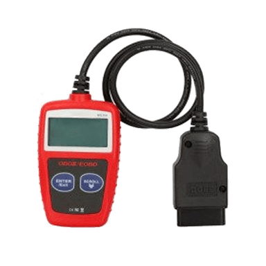
- OBD-II diagnostic scanner
- Nitrile mechanic gloves
- Safety glasses
🔩 Required Parts
HowToo sells all the parts you need for this repair:
- Mass air flow sensor with sealing O-ring - Qty: 1
📋 Before You Begin
- 🅿️ Park your Impala on level ground, select Park, and apply the parking brake.
- 🔑 Switch off the ignition and wait at least two minutes before unplugging the sensor.
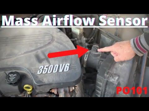
- 🔎 Open the hood and locate the MAF sensor in the air-intake tube immediately downstream of the engine air-filter housing.
- 🧰 An OBD-II scanner is a small diagnostic tool that plugs into the connector beneath the driver-side dashboard.
🔨 Step-by-Step Instructions
Follow these steps in order:
Step 1: Locate and Inspect the MAF Sensor
- Use a flashlight if needed to identify the rectangular electrical sensor installed in the upper side of the air-intake tube.
- Check that the surrounding intake tube is secure and not split or disconnected.
- Put on the safety glasses and nitrile mechanic gloves before handling the connector.
Step 2: Disconnect the Electrical Connector
- Locate the small connector-position lock on the MAF electrical plug.
- Use the plastic trim tool to slide the lock away from the sensor without forcing it.
- Press the connector release tab and pull the plug straight off by its plastic housing.
- Do not pull on the wires.
- Wiggle the housing gently if it sticks.
Step 3: Remove the Old MAF Sensor
- Use the Torx T20 screwdriver to loosen and remove the two MAF sensor retaining screws.
- Keep the screws clean because they will be reused unless replacements came with the sensor.
- Lift the sensor straight out of the intake tube.
- Do not twist it against the plastic opening or allow dirt to enter the intake.
Step 4: Prepare the New Sensor
- Compare the electrical connector, mounting holes, sensing probe, and airflow orientation of the new sensor with the removed sensor.
- Confirm that the new sealing O-ring is seated flat in its groove.
- Do not touch the sensing wires or electronics inside the probe.
- Handle the sensor only by its plastic body.
Step 5: Install the New MAF Sensor
- Position the new sensor in the intake opening in the same direction as the original.
- Press it down gently until the sealing O-ring sits evenly against the intake tube.
- Start both retaining screws by hand to prevent cross-threading.
- Use the 1/4-inch drive inch-pound torque wrench and Torx T20 bit socket to tighten both screws evenly to 1.5 Nm (13 lb-in).
- Do not overtighten the screws; the intake housing is plastic.
Step 6: Reconnect the Electrical Connector
- Push the electrical plug straight onto the new sensor until the release tab clicks.
- Use your fingers to return the connector-position lock to its locked position.
- Pull gently on the connector housing to confirm it is secure.
Step 7: Clear Stored Trouble Codes
- Connect the OBD-II diagnostic scanner to the diagnostic connector beneath the driver-side dashboard.
- Switch the ignition on without starting the engine.
- Use the scanner’s Diagnostics > Engine Control Module > Clear Trouble Codes function.
- Switch the ignition off and disconnect the scanner.
- If no scanner is available, the warning light may turn off after several successful drive cycles, but stored codes will remain in memory temporarily.
Step 8: Start and Check the Engine
- Start the engine and let it idle for three to five minutes without pressing the accelerator.
- Listen for a hissing sound that could indicate an intake-air leak.
- Confirm that the engine idles smoothly and the check-engine light does not return.
✅ After Repair
- ✅ Take a gentle 10-15 minute test drive and confirm normal acceleration and idle quality.
- 🔍 Recheck the electrical connector and sensor mounting area after the test drive.
- 🛠️ If the same fault returns, inspect the intake duct, air-filter housing, wiring, and connector terminals before replacing additional parts.
- ⚠️ Codes involving low reference voltage, open circuits, or implausible airflow may indicate a wiring or intake-leak problem rather than a defective new sensor.
💰 DIY vs Shop Cost
Shop Cost: ₹18,000-₹38,000 (parts + labor)
DIY Cost: ₹12,000-₹28,000 (parts only)
You Save: Approximately ₹6,000-₹10,000 by doing it yourself!
Local labor and imported-part prices vary. This repair takes a shop approximately 0.3-0.5 hour.
🎯 Ready to get started?
HowToo makes it easy: same-day/2-day shipping on every part, plus all the tools and specialty tools you need! Check out the parts and tools sections below to add everything to your cart.