

How to Replace the Alternator on a 2017-2020 Nissan Pathfinder 3.5L V6 (Engine: V6 3.5L)
Step-by-step DIY instructions with required tools, parts, torque specs, and safety tips for 2017, 2018, 2019, 2020
How to Replace the Alternator on a 2017-2020 Nissan Pathfinder 3.5L V6 (Engine: V6 3.5L)
Step-by-step DIY instructions with required tools, parts, torque specs, and safety tips for 2017, 2018, 2019, 2020


🔧 Pathfinder - Alternator Replacement
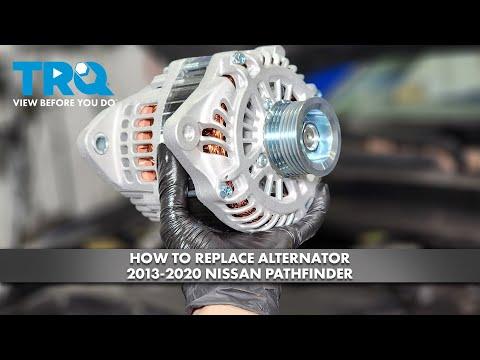
The alternator keeps the battery charged and powers the electrical system while the engine runs. On your Pathfinder, access requires removing the intake duct, electric cooling-fan assembly, drive belt, and temporarily moving the A/C compressor without opening the refrigerant system.
Difficulty Level: Advanced | Estimated Time: 4-6 hours
Assumption: This procedure is for the stock U.S.-market 3.5L V6 configuration; minor shield and bracket differences may occur.
⚠️ Safety & Precautions
- ⚠️ Disconnect the negative battery cable before touching the alternator wiring. The output terminal is always connected directly to the battery.
- 🧊 Allow the engine and exhaust system to cool completely before beginning.
- 🛑 Never work beneath your Pathfinder while it is supported only by a floor jack.
- 👓 Wear safety glasses and mechanic’s gloves throughout the repair.
- ❄️ Do not disconnect the A/C refrigerant lines. Move and support the compressor with its hoses attached.
- 🌀 Keep fingers and tools away from the electric cooling fans until the battery is disconnected.
- 🔩 Do not overtighten the alternator output-terminal nut; its insulated stud can break.
🔧 Required Tools
You'll need the following tools for this repair:
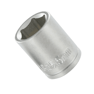
- 8mm socket
- 10mm socket
- 12mm socket
- 14mm socket
- 19mm six-point socket
- 3/8-inch-drive ratchet
- 1/2-inch-drive breaker bar
- 3-inch socket extension
- 6-inch socket extension
- 3/8-inch-drive torque wrench rated 5-80 Nm
- 1/2-inch-drive torque wrench rated 20-150 Nm
- Flat-blade screwdriver, 6-inch
- Nylon trim-clip removal tool
- Mechanic’s support wire rated 25 lb minimum
- Digital multimeter rated 20V DC minimum
- Floor jack rated 2-ton minimum
- Jack stands rated 2-ton minimum
- Wheel chocks rated 2-ton minimum
- LED work light
- Safety glasses
- Mechanic’s gloves
- Fender cover
🔩 Required Parts
HowToo sells all the parts you need for this repair:
- Alternator for 3.5L V6 - Qty: 1
- Serpentine drive belt - Qty: 1 if cracked, glazed, frayed, or contaminated
📋 Before You Begin
- 📍 Park your Pathfinder on firm, level ground. Select Park, apply the parking brake, and switch off all electrical accessories.
- 🛞 Place the wheel chocks securely behind both rear tires.
- 🧠 Save any radio presets you want to keep. Battery disconnection may reset the clock, automatic windows, and learned idle settings.
- 🔑 Keep the intelligent key away from the vehicle so the electrical system cannot be activated accidentally.
- 🔋 Wait at least three minutes after switching the ignition off before disconnecting the battery.
🔨 Step-by-Step Instructions
Follow these steps in order:
Step 1: Disconnect the Battery
- Place the fender cover over the painted bodywork.
- Use a 10mm socket and 3/8-inch-drive ratchet to loosen the negative battery-terminal nut.
- Lift the negative terminal from the battery post and position it where it cannot spring back into contact.
- Use the LED work light to verify that the cable is completely isolated.
Step 2: Raise and Support the Front
- Use the floor jack at the front-center lifting point, then place the jack stands beneath the approved front support points.
- Lower your Pathfinder gently onto the stands and confirm stability before going underneath.
- Use the nylon trim-clip removal tool and 10mm socket to remove the front engine-undercover clips and bolts.
- Set the undercover aside. During installation, tighten its bolts to 5.5 Nm (49 in-lbs).
Step 3: Remove the Air-Intake Duct
- Use the nylon trim-clip removal tool to release the intake-air duct retaining clips.
- If equipped with a clamp at the air-cleaner housing, loosen it with an 8mm socket and 3/8-inch-drive ratchet.
- Lift the duct out carefully and cover the open air-cleaner connection with a clean protective covering.
Step 4: Remove the Electric Cooling-Fan Assembly
- Use the flat-blade screwdriver to release each fan electrical-connector lock, then unplug the connectors by holding their housings rather than pulling the wires.
- Use the nylon trim-clip removal tool to release any wiring-harness and hose retainers attached to the fan shroud.
- Use a 10mm socket, extension, and 3/8-inch-drive ratchet to remove the fan-shroud fasteners.
- Lift the fan assembly straight upward while watching the radiator fins and hoses.
- During installation, tighten the fan-shroud fasteners to 5.5 Nm (49 in-lbs).
- Protect the radiator fins with thin cardboard.
Step 5: Record the Drive-Belt Routing
- Use the LED work light to locate the belt-routing label in the engine compartment.
- If the label is missing or unreadable, make a clear routing sketch before removing the belt.
- Inspect the belt with the LED work light. Replace it if it has exposed cords, missing ribs, heavy glazing, edge damage, or fluid contamination.
Step 6: Remove the Serpentine Belt
- The automatic tensioner is a spring-loaded pulley that maintains drive-belt tension.
- Fit the 19mm six-point socket and 1/2-inch-drive breaker bar onto the tensioner hex.
- Rotate the tensioner slowly clockwise to release belt tension, then slide the belt from one accessible pulley.
- Allow the tensioner to return slowly. Never let it snap back.
- Remove the belt from the remaining pulleys by hand.
Step 7: Move the A/C Compressor Aside
- Use the LED work light to identify the compressor mounting bolts below the alternator.
- Use a 14mm socket, extensions, and 3/8-inch-drive ratchet to remove the A/C compressor mounting bolts.
- Do not disconnect either refrigerant hose.
- Carefully move the compressor only far enough to create alternator clearance.
- Use mechanic’s support wire to suspend the compressor from a strong bracket. Do not allow its weight to hang from the hoses.
- During installation, tighten the compressor mounting bolts evenly to 25 Nm (18 ft-lbs).
Step 8: Disconnect the Alternator Wiring
- Use the flat-blade screwdriver to lift the protective cap from the alternator output terminal.
- Use a 12mm socket and 3/8-inch-drive ratchet to remove the output-terminal nut, then lift off the cable.
- Use the flat-blade screwdriver to release the alternator control-connector lock and unplug the connector by its housing.
- Use the nylon trim-clip removal tool to release any harness retainers from the alternator bracket.
- Move the wiring aside without sharply bending it.
Step 9: Remove the Alternator
- Support the alternator with one gloved hand.
- Use a 14mm socket, extension, and 3/8-inch-drive ratchet to remove the alternator mounting bolts.
- Work the alternator gently out of its mounting bracket. Do not pry against the radiator or aluminum engine components.
- Guide the alternator through the available opening created by moving the fan assembly and compressor.
- Compare the old and new alternators. Use the LED work light to verify matching mounting ears, pulley grooves, connector, and output-terminal position.
Step 10: Install the New Alternator
- Place the new alternator squarely into its mounting bracket by hand.
- Start every mounting bolt by hand for several turns to prevent cross-threading.
- Use a 14mm socket and 3/8-inch-drive ratchet to seat the bolts.
- Use the torque wrench and 14mm socket to tighten the alternator mounting bolts to 48 Nm (35 ft-lbs).
Step 11: Reconnect the Alternator Wiring
- Push the control connector into the alternator by hand until its lock clicks.
- Place the output cable squarely over the insulated terminal stud.
- Start the output-terminal nut by hand, then use the torque wrench and 12mm socket to tighten it to 10.8 Nm (95 in-lbs).
- Close the protective terminal cap by hand and reinstall each harness retainer with the nylon trim-clip removal tool.
Step 12: Reinstall the A/C Compressor
- Remove the mechanic’s support wire while supporting the compressor with one hand.
- Position the compressor against its bracket without twisting or trapping the refrigerant hoses.
- Start all compressor bolts by hand.
- Use the torque wrench, extension, and 14mm socket to tighten the bolts evenly to 25 Nm (18 ft-lbs).
Step 13: Install the Drive Belt
- Route the belt by hand according to the underhood diagram, leaving one smooth pulley for last.
- Use the 19mm six-point socket and 1/2-inch-drive breaker bar to rotate the tensioner clockwise.
- Slip the belt over the final pulley by hand, then release the tensioner slowly.
- Use the LED work light to confirm that every belt rib sits fully inside every grooved pulley.
- Check every pulley twice before starting.
Step 14: Reinstall the Cooling-Fan Assembly
- Lower the fan assembly into position by hand without scraping the radiator.
- Confirm that its lower locating tabs enter their mounting slots.
- Use the torque wrench and 10mm socket to tighten its fasteners to 5.5 Nm (49 in-lbs).
- Reconnect the fan electrical connectors by hand until their locks click.
- Reattach all harness and hose retainers using the nylon trim-clip removal tool.
Step 15: Reassemble the Intake and Undercover
- Install the intake duct by hand and engage its locating tabs.
- Use the nylon trim-clip removal tool to install its retaining clips.
- If equipped with an intake clamp, tighten it snugly with the 8mm socket and 3/8-inch-drive ratchet.
- Install the engine undercover using the nylon trim-clip removal tool and 10mm socket.
- Use the torque wrench and 10mm socket to tighten the undercover bolts to 5.5 Nm (49 in-lbs).
Step 16: Lower the Vehicle and Reconnect the Battery
- Use the floor jack to lift your Pathfinder slightly, remove both jack stands, and lower it fully.
- Install the negative battery terminal by hand.
- Use the torque wrench and 10mm socket to tighten the terminal nut to 5.4 Nm (48 in-lbs).
- Remove the wheel chocks and fender cover.
✅ After Repair
- 👀 Before starting, use the LED work light to make a final inspection for loose tools, disconnected fan plugs, trapped wiring, and incorrect belt routing.
- 🚗 Start the engine and watch the belt from a safe distance. It should run centrally and quietly without wandering or fluttering.
- 🔋 Set the digital multimeter to DC volts and place its probes across the battery terminals. A typical running voltage is approximately 13.5-14.8 volts, depending on battery condition and charging-system demand.
- 💡 Switch on the headlights and cabin blower, then verify that the charging warning lamp remains off.
- 🌀 Confirm that both cooling-fan connectors are secure. Allow the engine to reach operating temperature while watching the temperature gauge.
- 🪟 Reinitialize each automatic window if needed: close the window completely with its switch, then hold the switch in the closing direction for several seconds.
- 🕒 Reset the clock and restore saved audio settings.
- 🔍 After a short test drive, switch the engine off and inspect the belt and alternator area again.
💰 DIY vs Shop Cost
Shop Cost: $900-$1,500 (parts + labor)
DIY Cost: $350-$700 (parts only)
You Save: $550-$800 by doing it yourself!
Shop labor rates vary but typically run $100-$150/hour. This repair takes a shop approximately 2.5-4 hours.
🎯 Ready to get started?
HowToo makes it easy: same-day/2-day shipping on every part, plus all the tools and specialty tools you need! Check out the parts and tools sections below to add everything to your cart.