
How to Replace Front Strut Assemblies on a 2011-2013 Ford Explorer
Step-by-step DIY instructions with required tools, parts, torque specs, and safety tips for 2011, 2012, 2013
How to Replace Front Strut Assemblies on a 2011-2013 Ford Explorer
Step-by-step DIY instructions with required tools, parts, torque specs, and safety tips for 2011, 2012, 2013


🔧 Explorer - Front Strut Assembly Replacement
This procedure replaces both front struts on your Explorer. For a beginner, complete preassembled strut assemblies are strongly recommended because they include the spring, mount, and bearing and do not require a dangerous spring compressor.
Assumption: “Struts” refers to the front suspension; the rear uses separate shock absorbers.
Difficulty Level: Intermediate | Estimated Time: 3-5 hours
⚠️ Safety & Precautions
- ⚠️ Replace front struts in pairs so handling and braking remain balanced.
- ⚠️ Never work beneath your Explorer while it is supported only by a floor jack.
- ⚠️ Do not loosen the large center nut on top of the strut. The coil spring stores enough energy to cause severe injury.
- ⚠️ Use complete preassembled struts unless a trained technician with an approved spring compressor transfers the springs.
- ⚠️ Support the steering knuckle so the brake hose and wheel-speed sensor wire are not stretched.
- ⚠️ Do not allow the steering knuckle to pull outward far enough to separate an inner CV joint.
- ⚠️ A professional four-wheel alignment is required after replacement.
- 🔋 Battery disconnection is not required.
🔧 Required Tools
You'll need the following tools for this repair:
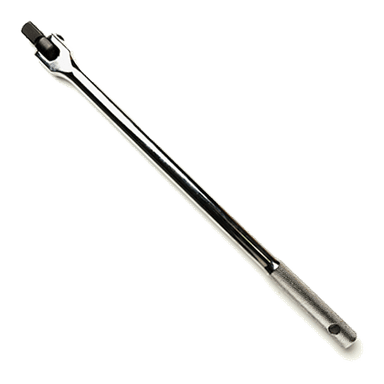
- 1/2-inch-drive breaker bar
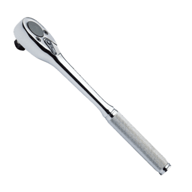
- 1/2-inch-drive ratchet
- 3/8-inch-drive ratchet
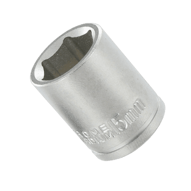
- 15mm socket
- 18mm socket
- 21mm deep socket
- 24mm socket
- 15mm combination wrench
- 18mm combination wrench
- 21mm combination wrench
- 5mm hex-bit socket
- 1/2-inch-drive torque wrench rated 250 ft-lbs
- 3/8-inch-drive torque wrench rated 10-80 ft-lbs
- 6-inch socket extension
- Floor jack rated 3-ton minimum
- Jack stands rated 3-ton minimum
- Wheel chocks
- Hydraulic support jack rated 2-ton minimum
- Medium pry bar
- 16-ounce ball-peen hammer
- Penetrating oil
- Paint marker
- Wire brush
- Mechanic’s gloves
- Safety glasses
🔩 Required Parts
HowToo sells all the parts you need for this repair:
- Front complete loaded strut assemblies - Qty: 2 - Replace in pairs
- Front strut-to-steering-knuckle bolts and nuts - Qty: 4
- Front stabilizer-bar link nuts - Qty: 2
- Penetrating lubricant - Qty: 1 can
📋 Before You Begin
- 🅿️ Park your Explorer on level, solid pavement. Shift into Park and apply the parking brake.
- Place wheel chocks firmly behind both rear tires.
- Open the hood and locate the three small upper-mount nuts surrounding each front strut tower. Do not touch the large center nut.
- Compare each replacement assembly with the matching side. Confirm the lower bracket and upper mounting studs have the same orientation.
- Apply penetrating oil to the stabilizer-link nut and the two large strut-to-knuckle fasteners. Allow it to soak for several minutes.
- No infotainment setting, scan-tool command, electronic parking-brake mode, or battery disconnect is required.
🔨 Step-by-Step Instructions
Follow these steps in order:
Step 1: Loosen the Front Wheel Nuts
- Use the 21mm deep socket and 1/2-inch-drive breaker bar to loosen each front wheel nut about one-half turn.
- Do not remove the wheel nuts while the tires are still supporting the vehicle.
Step 2: Raise and Support the Front
- Use the 3-ton floor jack at the front-center subframe lifting area to raise your Explorer.
- Position the 3-ton jack stands beneath the reinforced front-side support points.
- Lower the vehicle carefully onto the stands. Gently push the body to confirm it is stable.
- Keep the floor jack touching the subframe lightly as a backup, but do not let it carry the vehicle’s weight.
Step 3: Remove the Front Wheels
- Use the 21mm deep socket and 1/2-inch-drive ratchet to remove the wheel nuts.
- Remove both front wheels and slide them beneath the rocker-panel area as an additional safety measure.
Step 4: Release the Attached Brackets
- Use the 15mm socket and 3/8-inch-drive ratchet to remove the brake-hose and wheel-speed-sensor harness bracket fastener from the strut.
- Move the bracket aside without bending the brake hose or pulling on the electrical wire.
- A wheel-speed sensor detects wheel rotation for the ABS and stability-control systems.
Step 5: Disconnect the Stabilizer-Bar Link
- Use the 18mm combination wrench or 18mm socket to remove the stabilizer-bar link nut from the strut bracket.
- If the link stud turns, hold its center with the 5mm hex-bit socket while turning the nut with the 18mm combination wrench.
- Move the link stud out of the strut bracket. Do not force the link sideways.
- The stabilizer-bar link connects the suspension to the anti-roll bar and may be under slight tension.
Step 6: Mark and Support the Steering Knuckle
- Use the paint marker to draw alignment marks across the strut and steering-knuckle connection.
- Place the 2-ton hydraulic support jack beneath the lower control arm and raise it only enough to support the suspension.
- The steering knuckle is the heavy metal carrier holding the wheel hub and brake assembly.
Step 7: Remove the Lower Strut Fasteners
- Use the 24mm socket, 1/2-inch-drive breaker bar, and 24mm combination wrench to loosen the two strut-to-knuckle fasteners.
- Use the 16-ounce ball-peen hammer to tap the bolts out while supporting the knuckle with the hydraulic jack.
- Use the medium pry bar only if gentle movement is required to separate the strut bracket from the knuckle.
- Do not strike the threaded ends directly unless the old fasteners are being discarded.
- Do not let the knuckle fall outward or hang from the brake hose.
Step 8: Remove the Upper Strut-Mount Nuts
- Support the bottom of the strut with one hand.
- From under the hood, use the 15mm socket, 6-inch extension, and 3/8-inch-drive ratchet to remove the three upper-mount nuts.
- Do not loosen the large center nut.
- Guide the complete strut assembly downward and remove it through the wheel opening.
- Keep fingers clear as the last nut comes off.
Step 9: Position the New Strut Assembly
- Compare the old and new assemblies. Confirm the spring position, upper studs, lower bracket, and hose bracket match.
- Guide the replacement assembly through the wheel opening and place its three studs into the strut tower.
- Install the three new upper-mount nuts by hand. Do not fully tighten them yet.
- Use the 15mm socket and 3/8-inch-drive torque wrench to tighten the upper-mount nuts evenly to Torque to 41 Nm (30 ft-lbs).
Step 10: Connect the Strut to the Steering Knuckle
- Use the 2-ton hydraulic support jack to align the steering knuckle with the lower strut bracket.
- Install the new strut-to-knuckle bolts and nuts in the same direction as the originals.
- Use the 24mm socket, 24mm combination wrench, and 1/2-inch-drive torque wrench to tighten both fasteners to Torque to 250 Nm (184 ft-lbs).
- Keep the brake hose and wheel-speed-sensor wire clear of the spring, tire, and axle.
Step 11: Reconnect the Stabilizer-Bar Link
- Insert the stabilizer-link stud through the strut bracket.
- Use the 18mm socket and 1/2-inch-drive torque wrench to tighten the link nut to Torque to 133 Nm (98 ft-lbs).
- If the stud turns before the nut seats, hold it with the 5mm hex-bit socket and use the 18mm combination wrench. Complete final tightening with the torque wrench.
Step 12: Reinstall the Hose and Sensor Bracket
- Position the bracket exactly as it was before removal.
- Use the 15mm socket and 3/8-inch-drive torque wrench to tighten its fastener to Torque to 15 Nm (133 in-lbs).
- Check that the brake hose is not twisted and the wheel-speed-sensor wire is fully retained.
Step 13: Replace the Strut on the Opposite Side
- Repeat Steps 4 through 12 on the other side using the same listed tools.
- Keep removed parts separated by side to prevent mixing brackets or hardware.
Step 14: Install the Front Wheels
- Use the wire brush to remove loose rust from each wheel-to-hub mounting surface.
- Install the wheels and start every wheel nut by hand.
- Use the 21mm deep socket and 1/2-inch-drive ratchet to snug the nuts in a star pattern.
- Remove the safety wheels from beneath the vehicle.
Step 15: Lower the Vehicle and Torque the Wheels
- Use the 3-ton floor jack to raise your Explorer slightly and remove both jack stands.
- Lower the vehicle completely.
- Use the 21mm deep socket and 1/2-inch-drive torque wrench to tighten the wheel nuts in a star pattern to Torque to 135 Nm (100 ft-lbs).
✅ After Repair
- 🔍 Look through both wheel openings. Confirm every bracket is attached and no hose or wire touches a tire, spring, or axle.
- Start the engine and turn the steering wheel slowly from lock to lock. Stop if you hear binding, scraping, or a sharp pop.
- Drive slowly in a safe area. Check steering response, brake operation, and unusual suspension noise before reaching road speed.
- Arrange a professional four-wheel alignment immediately. Replacing struts can change camber and toe, which affects tire wear and steering.
- Recheck the front wheel-nut torque after approximately 80-160 km.
- If the ABS, traction-control, or steering warning light appears, stop and inspect the wheel-speed-sensor wiring before continuing.
💰 DIY vs Shop Cost
Shop Cost: ₹70,000-₹130,000 (parts + labor)
DIY Cost: ₹35,000-₹75,000 (parts only, excluding alignment)
You Save: ₹25,000-₹55,000 by doing it yourself!
Imported Explorer parts and local availability can change pricing substantially. This repair takes a shop approximately 3-4 hours, plus alignment.
🎯 Ready to get started?
HowToo makes it easy: same-day/2-day shipping on every part, plus all the tools and specialty tools you need! Check out the parts and tools sections below to add everything to your cart.