

How to Replace Front Lower Ball Joints on a 2016-2020 Kia Optima
Step-by-step DIY instructions with required tools, parts, torque specs, and safety tips for 2016, 2017, 2018, 2019, 2020
How to Replace Front Lower Ball Joints on a 2016-2020 Kia Optima
Step-by-step DIY instructions with required tools, parts, torque specs, and safety tips for 2016, 2017, 2018, 2019, 2020


🔧 Optima - Front Lower Ball Joint Replacement
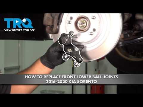
The front lower ball joints connect the steering knuckles to the lower control arms while allowing the wheels to steer and move with the suspension. On your Optima, each ball joint is a separately replaceable assembly secured to the lower control arm; replacing both sides together is recommended for balanced wear.
Difficulty Level: Advanced | Estimated Time: 3-5 hours
Assumption: These instructions cover both front lower ball joints.
⚠️ Safety & Precautions
- ⚠️ Support your Optima with jack stands. Never work beneath a vehicle supported only by a jack.
- ⚠️ The steering knuckle can drop when the joint separates. Support it so the brake hose and wheel-speed sensor wire are not stretched.
- ⚠️ Do not strike the threaded ball-joint stud or steering knuckle with a hammer.
- ⚠️ Keep grease and oil away from the brake rotor and pads.
- ⚠️ Replace self-locking nuts rather than reusing them.
- ⚠️ Battery disconnection is not required.
🔧 Required Tools
You'll need the following tools for this repair:
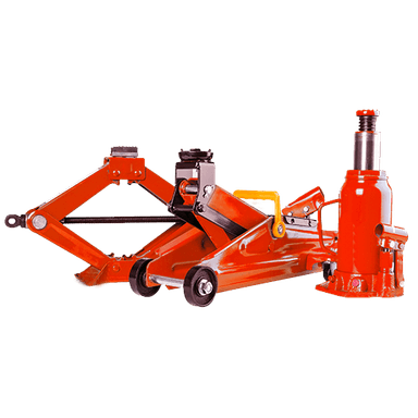
- Hydraulic floor jack rated 2-ton minimum
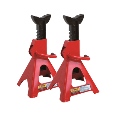
- Jack stands rated 2-ton minimum
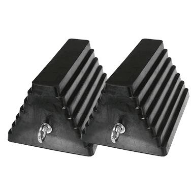
- Wheel chocks
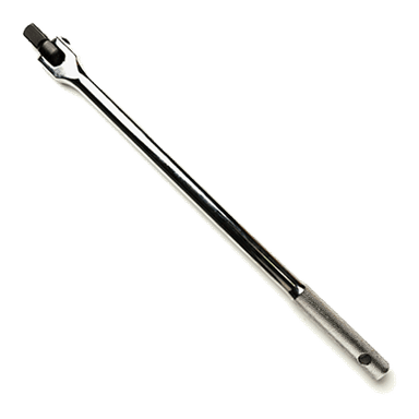
- 1/2-inch-drive breaker bar
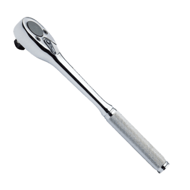
- 1/2-inch-drive ratchet
- 3/8-inch-drive ratchet
- 17mm deep socket
- 19mm deep socket
- 21mm deep socket
- 17mm combination wrench
- 19mm combination wrench
- 1/2-inch-drive extension set
- Torque wrench rated 20-150 Nm
- Ball-joint separator screw type (specialty)
- Small pry bar
- Soft-face mallet
- Flat-blade screwdriver
- Wire parts brush
- Mechanic’s wire rated 45kg minimum
- Penetrating oil aerosol
- Brake cleaner aerosol
- Paint marker
- Portable work light
- Safety glasses
- Mechanic’s gloves
🔩 Required Parts
HowToo sells all the parts you need for this repair:
- Front lower ball joint assemblies - Qty: 2 - Replace in pairs
- Ball-joint stud self-locking nuts - Qty: 2
- Ball-joint mounting self-locking nuts - Qty: 6
📋 Before You Begin
- 🚗 Park on firm, level ground. Select Park, apply the parking brake, and switch the engine off.
- Place wheel chocks firmly behind both rear tires.
- Spray penetrating oil on the ball-joint stud nut and three mounting nuts. Let it soak for 10-15 minutes.
- No infotainment service mode or scan-tool command is required.
- Plan for a professional wheel-alignment inspection after the repair.
🔨 Step-by-Step Instructions
Follow these steps in order:
Step 1: Loosen the Front Wheel Nuts
- Wear safety glasses and gloves.
- With the tires still touching the ground, use a 21mm deep socket and breaker bar to loosen each front wheel nut about one-half turn.
- Do not remove the nuts yet.
Step 2: Raise and Support the Front
- Place the hydraulic floor jack beneath the reinforced front-center lifting point.
- Raise your Optima and position both jack stands beneath the reinforced side support points.
- Lower the vehicle onto the stands, then gently push the body to verify it is stable.
- Keep the floor jack lightly touching the lifting point as an additional backup without carrying the vehicle’s weight.
Step 3: Remove Both Front Wheels
- Use the 21mm deep socket and ratchet to remove the wheel nuts.
- Lift off both wheels and place them flat away from your work area.
Step 4: Inspect the Ball-Joint Arrangement
- Use the portable work light to locate the joint between the steering knuckle and lower control arm.
- Use the wire parts brush and brake cleaner to expose the fasteners.
- Confirm that each replacement joint matches the original stud, mounting pattern, and dust-boot shape before disassembly.
- Use the paint marker to mark the original joint’s position on the control arm.
Step 5: Support the Steering Knuckle
- Loop mechanic’s wire around the steering knuckle and secure it to the strut spring seat.
- Leave enough slack for movement, but do not let the brake hose or wheel-speed sensor wire support the knuckle.
- Mechanic’s wire is strong reusable wire used to support suspension or brake components.
Step 6: Remove the Ball-Joint Stud Nut
- Use a 19mm deep socket and breaker bar to loosen the nut on the tapered ball-joint stud.
- If your installed fastener uses a 17mm head, use the 17mm deep socket instead.
- Remove the nut with the ratchet and discard it.
- A tapered stud is cone-shaped and locks tightly inside the steering knuckle.
Step 7: Separate the Stud from the Knuckle
- Install the screw-type ball-joint separator between the control arm and steering knuckle.
- Use the appropriate 17mm or 19mm wrench supplied by the separator design to tighten it slowly until the taper releases.
- Expect a sharp pop when the joint separates.
- Use the small pry bar only to create light clearance. Do not pull on the brake hose or pry against the joint’s dust shield.
- Keep fingers clear when the taper releases.
Step 8: Remove the Ball Joint from the Control Arm
- Use a 17mm deep socket and 17mm combination wrench to remove the three mounting nuts and bolts securing the joint to the lower control arm.
- If the original hardware uses 19mm heads, use the 19mm deep socket and combination wrench.
- Support the joint with one hand while removing the last fastener.
- Remove the joint. Use the soft-face mallet for light taps only if corrosion holds it in place.
Step 9: Clean and Inspect the Mounting Area
- Use the wire parts brush and brake cleaner to clean the control-arm mounting faces and steering-knuckle taper.
- Inspect the lower control arm for cracks, bent metal, enlarged holes, or severe rust.
- Inspect the steering-knuckle taper for damage. Stop the repair if either mounting surface is damaged.
- Do not apply grease or anti-seize to the tapered stud.
Step 10: Install the New Ball Joint
- Position the new joint against the lower control arm in the same orientation as the original and align it with the paint marks.
- Insert the three new mounting bolts and start the new nuts by hand.
- Use a 17mm socket and 17mm combination wrench to tighten the mounting hardware evenly.
- If the supplied hardware has 19mm heads, use the 19mm socket and wrench.
- Torque each ball-joint mounting fastener to 59-71 Nm (44-52 ft-lbs).
- Do not pinch or twist the rubber dust boot.
Step 11: Connect the Ball Joint to the Knuckle
- Guide the new tapered stud fully into the steering knuckle by hand.
- Install the new self-locking stud nut.
- Use a 19mm deep socket and torque wrench to tighten the stud nut.
- Torque the ball-joint stud nut to 88-108 Nm (65-80 ft-lbs).
- If the stud spins, use the floor jack to apply light upward pressure beneath the control arm while tightening. Do not lift the vehicle off the jack stand.
- Remove the mechanic’s wire after the joint is secure.
Step 12: Replace the Opposite Ball Joint
- Repeat Steps 4 through 11 on the other side using the same listed tools.
- Compare both sides before installing the wheels. Both dust boots must sit evenly and remain undamaged.
Step 13: Reinstall the Front Wheels
- Use the wire parts brush to clean the wheel-to-hub contact surfaces. Do not place lubricant on the studs or nuts.
- Install each wheel and start every wheel nut by hand.
- Use the 21mm deep socket and ratchet to snug the nuts in a crisscross pattern.
Step 14: Lower and Torque the Wheels
- Use the hydraulic floor jack to raise your Optima slightly, remove both jack stands, and lower the tires to the ground.
- Use the 21mm deep socket and torque wrench to tighten the wheel nuts in a crisscross pattern.
- Torque the wheel nuts to 107-127 Nm (79-94 ft-lbs).
✅ After Repair
- ✅ Turn the steering slowly from lock to lock while parked. Listen for knocks and confirm that nothing pulls on the brake hoses or sensor wires.
- Drive slowly in an open area. Check steering response and listen for clunks before entering normal traffic.
- Stop after a short drive and visually inspect both ball-joint boots and mounting points.
- Have the wheel alignment checked. Ball-joint replacement can reveal or alter existing suspension alignment problems.
- After 80-160 km, use the 21mm deep socket and torque wrench to verify wheel-nut torque.
- If the steering wheel is off-center, the vehicle pulls, or stability-control warnings appear, stop driving and have the suspension inspected.
💰 DIY vs Shop Cost
Shop Cost: ₹18,000-₹35,000 (parts + labor)
DIY Cost: ₹6,000-₹14,000 (parts only)
You Save: ₹12,000-₹21,000 by doing it yourself!
Local labor rates vary. This repair takes a shop approximately 2.5-4 hours, with wheel alignment commonly charged separately.
🎯 Ready to get started?
HowToo makes it easy: same-day/2-day shipping on every part, plus all the tools and specialty tools you need! Check out the parts and tools sections below to add everything to your cart.