


How to Replace Front Lower Ball Joints on a 2015-2022 Chevrolet Trax
Step-by-step guide for removing riveted joints, installing replacements, and applying torque specs for 2015, 2016, 2017, 2018, 2019, 2020, 2021, 2022
How to Replace Front Lower Ball Joints on a 2015-2022 Chevrolet Trax
Step-by-step guide for removing riveted joints, installing replacements, and applying torque specs for 2015, 2016, 2017, 2018, 2019, 2020, 2021, 2022


🔧 Trax - Front Lower Ball Joint Replacement
The front lower ball joints connect the steering knuckles to the lower control arms. The factory joints are riveted to the arms, so their rivets must be drilled out before bolt-on replacement joints can be installed.
Difficulty Level: Advanced | Estimated Time: 3-5 hours for both sides
Assumption: This procedure covers replacing both original, riveted front lower ball joints.
⚠️ Safety & Precautions
- ⚠️ Support your Trax with jack stands on the reinforced front lifting points. Never work under a vehicle supported only by a jack.
- ⚠️ Wear safety glasses while drilling or hammering the factory rivets. Sharp metal fragments can be ejected.
- ⚠️ Keep the steering knuckle supported. Do not allow it to hang from the brake hose or ABS wheel-speed sensor wire.
- ⚠️ Do not strike the threaded end of the new ball-joint stud.
- ⚠️ Final tightening of the ball-joint fasteners must use a torque wrench.
- 🔋 Battery disconnection is not required.
🔧 Required Tools
You'll need the following tools for this repair:
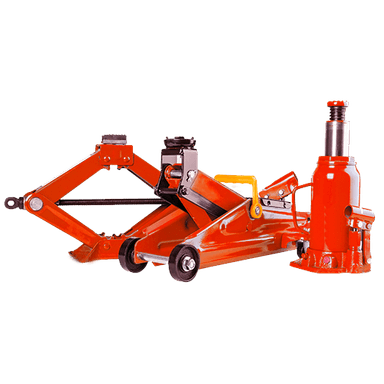
- Hydraulic floor jack rated 2-ton minimum
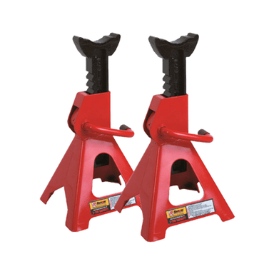
- Jack stands rated 2-ton minimum
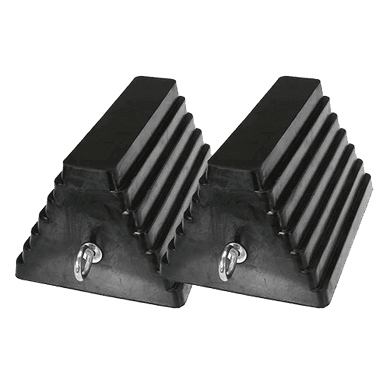
- Wheel chocks sized for passenger vehicles
- 19mm impact socket
- 13-19mm metric socket set
- 13-19mm metric combination wrench set
- 1/2-inch-drive breaker bar
- 3/8-inch-drive ratchet
- Torque wrench rated 20-150 Nm
- Lower ball-joint separator (specialty)
- Electric drill rated 1/2-inch chuck
- 3mm cobalt drill bit
- 6mm cobalt drill bit
- 10mm cobalt drill bit
- 12mm cobalt drill bit
- Center punch 6mm
- Cold chisel 12mm
- Ball-peen hammer 16-ounce
- Pry bar 450mm
- Wire brush 25mm
- Needle-nose pliers 150mm
- Penetrating oil aerosol
- Medium-strength threadlocker
- Mechanic gloves
- Safety glasses with side shields
- Hearing protection rated 20dB minimum
🔩 Required Parts
HowToo sells all the parts you need for this repair:
- Front lower ball joints with installation hardware - Qty: 2
- Steering-knuckle ball-joint pinch bolts and nuts - Qty: 2
- Ball-joint cotter pins - Qty: 2, only if supplied joints use castellated nuts
Replace in pairs: Replacing both front ball joints is recommended because they have the same age and mileage. Use joints specifically designed to replace the Trax’s factory riveted joints.
📋 Before You Begin
- 🅿️ Park your Trax on solid, level ground. Place the transmission in Park and apply the parking brake.
- 🛞 Place wheel chocks securely behind both rear tires.
- 📏 Arrange for a front-wheel alignment after the repair.
- 🔍 Verify that each replacement joint includes three mounting bolts, locking nuts and the correct stud hardware.
- 🧰 A ball-joint separator is a tool that safely pushes the tapered joint stud out of the steering knuckle.
- 📱 No infotainment service mode or scan-tool command is required.
🔨 Step-by-Step Instructions
Follow these steps in order:
Step 1: Loosen the Front Wheel Nuts
- Use the 19mm impact socket and 1/2-inch-drive breaker bar to loosen each front wheel nut approximately one-half turn.
- Do not remove the nuts while your Trax is still on the ground.
Step 2: Raise and Support the Front
- Use the hydraulic floor jack rated 2-ton minimum at the front-center lifting point.
- Place the jack stands rated 2-ton minimum beneath the reinforced front side lifting points.
- Lower the vehicle onto the stands and gently push the body to confirm it is stable.
- Leave the floor jack lightly touching as backup.
Step 3: Remove the Front Wheels
- Use the 19mm impact socket and 3/8-inch-drive ratchet to remove the wheel nuts.
- Remove both front wheels and slide them away from the work area.
Step 4: Support the Steering Knuckle
- Turn the steering wheel to create working room on the first side.
- Position the hydraulic floor jack rated 2-ton minimum under the outer end of the lower control arm. Raise it only enough to support the arm.
- Inspect the brake hose and ABS sensor wire. They must remain loose and must not support the knuckle.
Step 5: Remove the Ball-Joint Pinch Bolt
- Spray the knuckle’s ball-joint pinch bolt with penetrating oil aerosol and allow it to soak.
- Use the appropriate tools from the 13-19mm metric socket set and 13-19mm metric combination wrench set to remove the horizontal pinch-bolt nut and bolt.
- Discard the removed pinch bolt and nut if replacements are available. This fastener clamps the knuckle around the ball-joint stud.
Step 6: Separate the Joint from the Knuckle
- Install the lower ball-joint separator between the joint and steering knuckle.
- Tighten the separator with the appropriate socket from the 13-19mm metric socket set until the stud releases.
- Use the 450mm pry bar to push the lower control arm down while guiding the stud out of the knuckle.
- Support the knuckle immediately. Do not stretch the brake hose or ABS sensor wire.
- Avoid hammering directly on the steering knuckle.
Step 7: Drill Out the Factory Rivets
- Put on the safety glasses with side shields, mechanic gloves and hearing protection rated 20dB minimum.
- Use the 6mm center punch and 16-ounce ball-peen hammer to mark the center of each of the three factory rivets.
- Use the electric drill rated 1/2-inch chuck and 3mm cobalt drill bit to make a pilot hole through each rivet head.
- Enlarge each hole gradually using the 6mm, 10mm and then 12mm cobalt drill bits. Stop when the rivet head separates from its shank.
- Use the 12mm cold chisel and 16-ounce ball-peen hammer to remove the remaining rivet heads.
- Use the 6mm center punch and hammer to drive the rivet shanks out of the control arm.
- Drill slowly to avoid overheating the bits.
Step 8: Remove the Old Ball Joint
- Pull the old ball joint away from the underside of the lower control arm.
- Use the 25mm wire brush to remove rust and rivet debris from the control-arm mounting surface.
- Inspect the control arm for cracks, enlarged holes or heavy corrosion. Replace the complete control arm if any damage is found.
Step 9: Install the New Ball Joint
- Position the replacement ball joint against the underside of the control arm in the same orientation as the original.
- Insert the supplied mounting bolts in the direction specified by the joint manufacturer. Keep bolt ends clear of the CV axle boot and steering knuckle.
- Apply a small amount of medium-strength threadlocker only if the supplied hardware is not already self-locking and the joint instructions permit it.
- Use the appropriate tools from the 13-19mm metric socket set and 13-19mm metric combination wrench set to tighten all three fasteners evenly.
- Use the torque wrench rated 20-150 Nm to tighten the mounting hardware to 55 Nm (41 ft-lbs), unless the replacement-joint instructions specify a different torque. The joint manufacturer’s specification takes priority for supplied hardware.
Step 10: Connect the Joint to the Steering Knuckle
- Use the 450mm pry bar to lower the control arm enough to align the new stud with the knuckle.
- Guide the stud fully into the knuckle. Align its machined groove with the pinch-bolt opening.
- Install the new pinch bolt and nut. Never force the bolt past a misaligned stud.
- Use the appropriate tools from the 13-19mm metric socket set and 13-19mm metric combination wrench set, followed by the torque wrench rated 20-150 Nm, to tighten the pinch bolt to 60 Nm (44 ft-lbs).
- If the replacement design uses a castellated stud nut, tighten it to the joint manufacturer’s stated torque, then use the 150mm needle-nose pliers to install a new cotter pin. Never loosen the nut to align the cotter-pin hole.
Step 11: Repeat on the Opposite Side
- Repeat Steps 4 through 10 using the same listed tools and new hardware.
- Check that both ball joints sit flat against their control arms and that no hardware contacts either CV axle boot.
Step 12: Reinstall the Wheels
- Install each wheel and start all five nuts by hand.
- Use the 19mm impact socket and 3/8-inch-drive ratchet to snug the nuts in a star pattern. Do not final-torque them while raised.
- Use the hydraulic floor jack rated 2-ton minimum to lift your Trax, remove the jack stands and lower it completely.
- Use the 19mm impact socket and torque wrench rated 20-150 Nm to tighten the wheel nuts in a star pattern to 140 Nm (100 ft-lbs).
✅ After Repair
- 🔍 Turn the steering fully left and right while parked. Confirm there is no binding, scraping or contact with the CV axle boots.
- 🛞 Drive slowly in a safe area and listen for clunks. Stop immediately if the steering feels loose or unstable.
- 📏 Have a four-wheel alignment performed. Control-arm movement can change front toe, which affects tire wear and steering stability.
- 🔧 Recheck the wheel-nut torque at 140 Nm (100 ft-lbs) after approximately 80-160 km.
- ⚠️ Inspect the new mounting hardware after the first short drive. Any movement or looseness requires immediate correction.
💰 DIY vs Shop Cost
Shop Cost: ₹20,000-₹38,000 (parts + labor)
DIY Cost: ₹7,000-₹16,000 (parts only)
You Save: ₹13,000-₹22,000 by doing it yourself!
Independent labor rates around Sonīpat commonly run approximately ₹800-₹2,000 per hour. Imported Trax parts and availability can significantly affect the total. This repair takes a shop approximately 2.5-4 hours.
🎯 Ready to get started?
HowToo makes it easy: same-day/2-day shipping on every part, plus all the tools and specialty tools you need! Check out the parts and tools sections below to add everything to your cart.