
How to Replace Front Lower Ball Joints on a 2011-2019 Ford Explorer
Step-by-step control arm replacement with required tools, parts, torque specs, and safety tips for 2011, 2012, 2013, 2014, 2015, 2016, 2017, 2018, 2019
How to Replace Front Lower Ball Joints on a 2011-2019 Ford Explorer
Step-by-step control arm replacement with required tools, parts, torque specs, and safety tips for 2011, 2012, 2013, 2014, 2015, 2016, 2017, 2018, 2019


🔧 Explorer - Front Lower Ball Joint Replacement
On your Explorer, the front lower ball joint is serviced with the complete lower control arm assembly. Replacing the control arm avoids pressing the joint in and out, and it also renews both control-arm bushings. The procedure below covers replacing both front lower control arms.
Difficulty Level: Advanced | Estimated Time: 4-6 hours
Assumption: This procedure is for the front lower ball joints; your Explorer does not use separate front upper ball joints.
⚠️ Safety & Precautions
- ⚠️ Support your Explorer with jack stands on solid, level ground. Never work under a vehicle supported only by a jack.
- ⚠️ The steering knuckle can move suddenly after the ball joint separates. Support it and keep your fingers out of pinch points.
- ⚠️ Do not let the steering knuckle hang from the brake hose, ABS sensor wire, or CV axle.
- ⚠️ Do not strike the threaded end of the ball-joint stud with a hammer.
- ⚠️ Final control-arm bushing tightening must be performed at normal ride height. Tightening with the suspension hanging can damage the new bushings.
- ⚠️ Replace the ball-joint retaining nut and any control-arm fasteners supplied as one-time-use hardware.
- 🔋 Battery disconnection is not required.
🔧 Required Tools
You'll need the following tools for this repair:
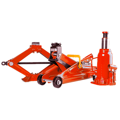
- 2-ton floor jack
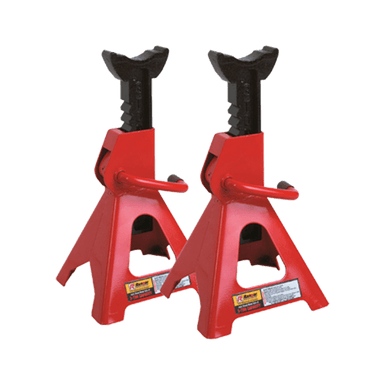
- 2-ton jack stands
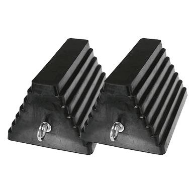
- Rubber wheel chocks
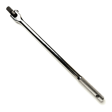
- 1/2-inch drive breaker bar
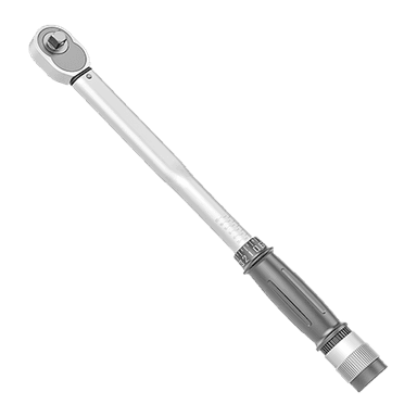
- 1/2-inch drive torque wrench rated 250 Nm minimum
- 3/8-inch drive ratchet
- 15mm socket
- 18mm socket
- 21mm socket
- 24mm socket
- 15mm combination wrench
- 18mm combination wrench
- 21mm combination wrench
- 24mm combination wrench
- 6mm hex-bit socket
- Front-wheel-drive ball-joint separator (specialty)
- Medium pry bar
- 16-ounce ball-peen hammer
- Brass wire brush
- Penetrating oil
- Paint marker
- Support strap rated 450kg minimum
- Mechanic’s gloves
- Safety glasses
🔩 Required Parts
HowToo sells all the parts you need for this repair:
- Front left lower control arm with ball joint - Qty: 1
- Front right lower control arm with ball joint - Qty: 1
- Lower ball-joint retaining nuts - Qty: 2
- Lower control-arm mounting hardware set - Qty: 2
Replace in pairs: Replacing both sides keeps bushing movement and steering response balanced.
📋 Before You Begin
- 📍 Park your Explorer on firm, level ground. Put the transmission in Park and apply the parking brake.
- 🛞 Chock both rear wheels with rubber wheel chocks.
- 📱 No infotainment service mode or scan-tool command is required.
- 🔩 Use a paint marker to mark each front wheel’s position relative to its hub.
- 🧰 A ball-joint separator is a screw-operated tool that pushes the tapered stud out of the steering knuckle without hammering on the stud.
- 📐 Arrange a four-wheel alignment after the repair. Control-arm replacement can change toe and steering-wheel position.
🔨 Step-by-Step Instructions
Follow these steps in order:
Step 1: Loosen the Front Wheel Nuts
- Use the rubber wheel chocks behind both rear wheels.
- Use a 21mm socket and 1/2-inch drive breaker bar to loosen each front wheel nut approximately one-quarter turn.
- Do not remove the wheel nuts while your Explorer is on the ground.
Step 2: Raise and Support the Front
- Use the 2-ton floor jack under the approved front-center lifting point to raise your Explorer.
- Place the 2-ton jack stands beneath the reinforced front side lifting points.
- Lower your Explorer onto the stands with the 2-ton floor jack, then gently push the body to confirm it is stable.
Step 3: Remove Both Front Wheels
- Use the 21mm socket and 3/8-inch drive ratchet to remove the wheel nuts.
- Remove both wheels and place them flat away from the work area.
- Use the brass wire brush to clean rust from the visible ball-joint stud and mounting fasteners.
- Apply penetrating oil to the ball-joint nut and control-arm fasteners.
Step 4: Support the Steering Knuckle
- Loop the support strap rated 450kg minimum around the steering knuckle and secure it to the strut spring.
- Leave enough slack for limited movement, but do not allow the brake hose or ABS sensor wire to carry any weight.
- Use the 2-ton floor jack beneath the control arm to support it lightly.
Step 5: Disconnect the Stabilizer-Bar Link if Needed
- If the stabilizer-bar link prevents the arm from dropping, use a 15mm wrench on the link nut and a 6mm hex-bit socket to hold the stud.
- Move the link clear without pulling on its rubber boots.
- Clean exposed threads before turning the nut.
Step 6: Remove the Lower Ball-Joint Nut
- Use a 21mm or 24mm socket, matching the installed service nut, with the 1/2-inch drive breaker bar to remove the lower ball-joint nut.
- Discard the removed nut. Do not reuse a prevailing-torque nut, which is a locknut designed to resist loosening.
- Do not loosen the front axle nut; axle removal is not required for this repair.
Step 7: Separate the Ball Joint
- Position the front-wheel-drive ball-joint separator between the lower control arm and steering knuckle.
- Use the correctly sized wrench from the tool list to tighten the separator until the tapered stud releases.
- If necessary, use the 16-ounce ball-peen hammer to tap the side of the knuckle boss while the separator is loaded.
- Do not strike the ball-joint stud, brake rotor, ABS sensor, or CV axle.
- Lower the 2-ton floor jack slowly and guide the stud out of the knuckle with the medium pry bar.
Step 8: Remove the Lower Control Arm
- Use the paint marker to mark the orientation of the original mounting bolts and washers.
- Use the matching 18mm, 21mm, or 24mm socket and combination wrench to remove the front and rear control-arm mounting fasteners.
- Support the arm with one hand as the final bolt is removed. The assembly is heavier than it appears.
- Use the medium pry bar carefully to release the bushings from the subframe pockets.
- Do not bend the subframe mounting tabs.
Step 9: Compare and Install the New Control Arm
- Place the old and new arms side by side. Confirm the ball-joint stud, bushing widths, mounting holes, and left-or-right orientation match.
- Use the medium pry bar to guide the new bushings into the subframe pockets.
- Install the new control-arm bolts and nuts by hand. Do not fully tighten them yet.
- Use the 2-ton floor jack to raise the arm, then guide the ball-joint stud into the steering knuckle.
- Install the new ball-joint nut by hand to avoid cross-threading.
Step 10: Tighten the Ball-Joint Connection
- Use the appropriate 21mm or 24mm socket and 1/2-inch drive torque wrench on the new ball-joint nut.
- Torque the lower ball-joint nut to 200 Nm (148 ft-lbs).
- If the replacement arm manufacturer specifies a different torque for supplied hardware, follow that documented specification.
Step 11: Reconnect the Stabilizer-Bar Link
- Use the 15mm wrench and 6mm hex-bit socket to reconnect the stabilizer-bar link if it was removed.
- Torque the stabilizer-bar link nut to 63 Nm (46 ft-lbs).
- Check that the rubber boots are not twisted or pinched.
Step 12: Repeat on the Opposite Side
- Use the same tools and procedure to replace the other front lower control arm.
- Keep left-side and right-side parts separate because the arms are not interchangeable.
Step 13: Reinstall the Front Wheels
- Use the brass wire brush to clean the wheel-to-hub mounting surfaces. Do not apply grease or anti-seize.
- Align the paint marks and install each wheel.
- Use the 21mm socket and 3/8-inch drive ratchet to snug the wheel nuts in a star pattern.
- Use the 2-ton floor jack to remove the jack stands and lower your Explorer onto the ground.
Step 14: Tighten at Normal Ride Height
- With the full vehicle weight on the wheels, roll your Explorer forward and backward approximately one metre to settle the suspension.
- Use the matching 18mm, 21mm, or 24mm socket, combination wrench, and 1/2-inch drive torque wrench to tighten the control-arm mounting fasteners.
- Torque the lower control-arm-to-subframe fasteners to 175 Nm (129 ft-lbs).
- Access may be limited with the vehicle on the ground. Use a professional drive-on lift if the torque wrench cannot be positioned safely.
- Never crawl under an unsupported vehicle.
Step 15: Torque the Wheel Nuts
- Use the 21mm socket and 1/2-inch drive torque wrench.
- Tighten the wheel nuts gradually in a star pattern.
- Torque the wheel nuts to 135 Nm (100 ft-lbs).
✅ After Repair
- 🔍 Turn the steering slowly from lock to lock and verify that no hose, wire, or link is stretched or rubbing.
- 🚗 Drive slowly in a safe area. Listen for clunks and confirm that the steering wheel returns normally after a turn.
- 🛑 Stop immediately if the steering feels loose, the vehicle pulls sharply, or a knocking sound is present.
- 📐 Have a four-wheel alignment performed before normal or highway driving.
- 🔧 Recheck the wheel-nut torque after approximately 80-160 km.
- 🔎 Inspect the ball-joint boots after the road test. They must remain seated and undamaged.
💰 DIY vs Shop Cost
Shop Cost: ₹35,000-₹65,000 (parts + labor)
DIY Cost: ₹18,000-₹38,000 (parts only)
You Save: ₹17,000-₹27,000 by doing it yourself!
Labor rates around Sonīpat vary widely. This repair takes a shop approximately 3-5 hours, plus wheel alignment.
🎯 Ready to get started?
HowToo makes it easy: same-day/2-day shipping on every part, plus all the tools and specialty tools you need! Check out the parts and tools sections below to add everything to your cart.