
How to Replace Front Lower Ball Joints on a 2009-2014 Ford F-150 4WD (Trim: STX)
Step-by-step instructions with required tools, parts, torque specs, and safety tips for 2009, 2010, 2011, 2012, 2013, 2014
How to Replace Front Lower Ball Joints on a 2009-2014 Ford F-150 4WD (Trim: STX)
Step-by-step instructions with required tools, parts, torque specs, and safety tips for 2009, 2010, 2011, 2012, 2013, 2014


🔧 F-150 - Front Ball Joint Replacement
This procedure covers replacing the front lower ball joint on your F-150’s 4WD suspension. The upper ball joint is permanently built into the upper control arm, so a worn upper joint requires replacing the complete upper control arm.
Assumption: The lower ball joint is being replaced; repeat the procedure on the opposite side if both are worn.
Difficulty Level: Advanced | Estimated Time: 3-5 hours per side
⚠️ Safety & Precautions
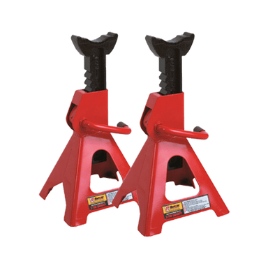
- ⚠️ Support your F-150 by the frame using correctly rated jack stands. Never work under a vehicle supported only by a jack.
- ⚠️ The front coil-over spring remains installed. Do not loosen its center shaft nut or attempt to disassemble it.
- ⚠️ Support the steering knuckle before separating either ball joint so it cannot fall or pull on the brake hose.
- ⚠️ Do not strike the wheel hub, CV axle threads, or steering knuckle with a steel hammer.
- ⚠️ Keep grease and penetrating oil away from the brake rotor and pads.
- ⚠️ Use a new axle nut and new prevailing-torque ball-joint nuts. These locking fasteners should not be reused.
- ⚠️ Final fastener torque must be checked against the instructions supplied with the replacement joint because aftermarket stud and nut designs can differ.
- ⚠️ A wheel alignment is required if the upper control arm is replaced. An alignment check is strongly recommended after lower-joint replacement.
- 🔋 Battery disconnection is not required.
🔧 Required Tools
You'll need the following tools for this repair:
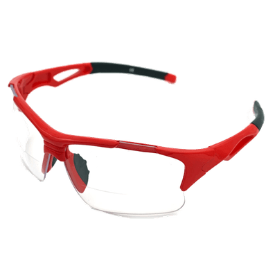
- Safety glasses
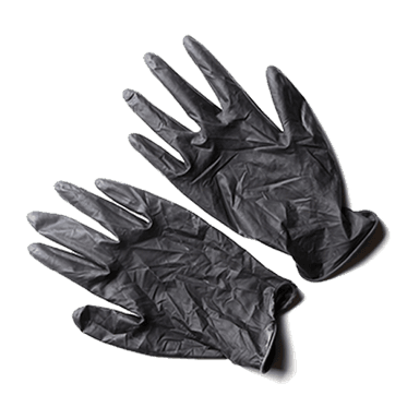
- Mechanic’s gloves
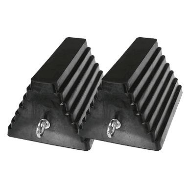
- Wheel chocks
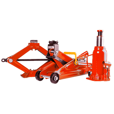
- Floor jack (rated 3-ton minimum)
- Jack stands (rated 3-ton minimum)
- 1/2-inch drive breaker bar
- 1/2-inch drive torque wrench (rated 250 ft-lbs minimum)
- 3/8-inch drive torque wrench (rated 100 ft-lbs minimum)
- 21mm deep socket
- 22mm deep socket
- 30mm axle-nut socket
- 8mm socket
- 10mm socket
- 13mm socket
- 15mm socket
- 18mm socket
- 21mm combination wrench
- 24mm combination wrench
- 3/8-inch drive ratchet
- 1/2-inch drive ratchet
- 6-inch socket extension
- Flat-blade screwdriver
- Needle-nose pliers
- Side-cutting pliers
- Ball-joint separator (specialty)
- C-frame ball-joint press (specialty)
- Ford truck ball-joint press adapter set (specialty)
- Hub puller (specialty)
- Brass drift
- 3-pound dead-blow hammer
- Medium pry bar
- Snap-ring pliers
- Brake-caliper hanger
- Wire brush
- Paint marker
- Grease gun
🔩 Required Parts
HowToo sells all the parts you need for this repair:
- Front lower ball joint - Qty: 1 per side
- Front lower ball-joint locking nut - Qty: 1 per side
- Front CV axle nut - Qty: 1 per side
- Ball-joint retaining snap ring - Qty: 1 per side
- Ball-joint grease fitting - Qty: 1 per side if supplied
- NLGI No. 2 chassis grease - Qty: 1 cartridge if required
- Penetrating oil - Qty: 1 can
- Brake cleaner - Qty: 1 can
- Front upper control arm assembly - Qty: 1 per side only if the upper joint is worn
Recommended: Replace lower ball joints in pairs when both sides have similar mileage or looseness.
📋 Before You Begin
- 📍 Park your F-150 on firm, level ground. Shift to Park, engage the parking brake, and switch 4WD to 2H.
- 🛞 Place wheel chocks tightly behind both rear tires.
- 🔩 Loosen the front wheel lug nuts one-half turn with a 21mm socket while the tire remains on the ground.
- 🔩 Loosen the front axle nut with a 30mm socket and breaker bar while the vehicle’s weight prevents the hub from turning. Do not remove it yet.
- 🧰 A ball-joint press is a large screw-operated C-frame used to push a press-fit joint out of and into the control arm.
- 🧰 Check that the press adapter kit has cups large enough to support the F-150 lower control arm without loading its thin edges.
- 📋 Read the replacement joint’s instructions before installation. Follow its supplied nut specification when it differs from the original-style fastener.
🔨 Step-by-Step Instructions
Follow these steps in order:
Step 1: Raise and Support the Front
- Use the floor jack under the front crossmember to raise your F-150.
- Place both 3-ton jack stands beneath the frame rails, then lower the truck slowly onto them.
- Give the vehicle a firm push to confirm it is stable before working near the suspension.
- Use the floor jack beneath the lower control arm as a light secondary support. Do not lift the truck away from the jack stand.
Step 2: Remove the Wheel
- Use the 21mm deep socket and 1/2-inch ratchet to remove the six lug nuts.
- Remove the wheel and slide it beneath the frame as an additional safety measure.
- Keep the lug nuts together in a tray.
Step 3: Remove the Brake Caliper and Rotor
- Use the appropriate 18mm or 21mm socket for the installed caliper-bracket bolts and remove both bolts.
- Lift the caliper and bracket from the rotor. Hang it from the frame with the brake-caliper hanger.
- Do not allow the caliper to hang by its rubber brake hose.
- Pull the rotor from the hub. If stuck, use the 3-pound dead-blow hammer around the rotor hat between the studs.
- Do not open the hydraulic brake system.
Step 4: Free the ABS Harness
- Use an 8mm or 10mm socket, as fitted, to remove the wheel-speed sensor harness retaining bolts from the knuckle.
- Use the flat-blade screwdriver to release the harness clips without pulling on the wires.
- Move the harness aside so it cannot be stretched when the knuckle moves.
Step 5: Disconnect the Outer Tie-Rod End
- Use needle-nose pliers or side-cutting pliers to remove the cotter pin if the installed tie-rod end uses one.
- Use the correct 21mm or 22mm socket to loosen the tie-rod stud nut until it is flush with the stud end.
- Install the ball-joint separator between the tie-rod end and steering arm, then tighten it until the taper releases.
- Remove the nut with the same socket and move the tie rod aside.
- During assembly, tighten an original-style outer tie-rod nut to 85 Nm (63 ft-lbs), then align the next cotter-pin opening if applicable. Use the part maker’s specification if its replacement nut differs.
Step 6: Release the CV Axle From the Hub
- Use the 30mm axle-nut socket to remove and discard the old axle nut.
- Thread the old nut back onto the axle until it is flush with the end. Use a brass drift and dead-blow hammer to start the axle moving inward.
- If it will not move easily, install the hub puller and press the axle inward. Do not hammer directly on its threads.
- Remove the old nut again after the axle splines move freely.
Step 7: Separate the Upper Ball Joint
- Place the floor jack under the outer end of the lower control arm and lift lightly to support the knuckle.
- Use the correct 18mm or 21mm socket to loosen the upper ball-joint nut until it is flush with the stud.
- Use the ball-joint separator to release the tapered stud from the knuckle.
- Remove the nut with the same socket, then carefully swing the knuckle outward while guiding the CV axle from the hub.
- Secure the knuckle with the brake-caliper hanger. Do not stretch the brake hose or ABS harness.
- During assembly, tighten an original-style upper ball-joint nut to 115 Nm (85 ft-lbs). Follow the control-arm manufacturer’s specification if its supplied fastener differs.
Step 8: Separate the Lower Ball Joint
- Keep the knuckle supported with the brake-caliper hanger and floor jack.
- Use the correct 24mm socket or wrench to loosen the lower ball-joint nut until it remains engaged by several threads.
- Install the ball-joint separator and tighten it until the tapered stud releases from the steering knuckle.
- Remove the nut with the 24mm socket and lift the knuckle from the lower stud.
- Move the knuckle aside without sharply bending the brake hose.
Step 9: Remove the Old Lower Ball Joint
- Use the wire brush to clean dirt and rust from the ball joint and retaining-ring groove.
- Use snap-ring pliers to remove the retaining snap ring from the top of the joint, if equipped.
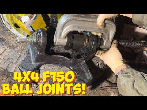
- Position the C-frame ball-joint press with the correct Ford truck receiver cup beneath the joint. The receiver must support the control arm while leaving room for the joint to exit.
- Use the correct socket and breaker bar on the press screw to push the old joint downward and out of the lower control arm.
- Stop immediately if the press tilts or the control arm begins to deform. Reposition the adapters squarely before continuing.
- Never use an impact wrench on a crooked press.
Step 10: Install the New Lower Ball Joint
- Use brake cleaner and a wire brush to clean the control-arm bore. Do not grind or enlarge it.
- Compare the new and old joints. Confirm the stud taper, body diameter, shoulder, and retaining-ring location match.
- Orient the new joint exactly as directed by its manufacturer, especially if it has a grease-relief slot or angled fitting.
- Position the C-frame ball-joint press and Ford truck installation adapters so pressure is applied only to the joint’s outer metal flange.
- Use the correct socket and breaker bar to press the joint squarely into the arm until its shoulder is fully seated.
- Use snap-ring pliers to install the new snap ring. Confirm it is completely seated around the groove.
- If supplied, use the specified wrench to install the grease fitting gently. Do not overtighten the small fitting.
- Use the grease gun to add NLGI No. 2 chassis grease only until the boot begins to swell. Do not rupture the boot.
Step 11: Reconnect the Lower and Upper Ball Joints
- Use the floor jack to support and position the lower control arm.
- Guide the lower ball-joint stud into the knuckle by hand. Keep the rubber dust boot from being pinched.
- Install the new lower-joint nut and tighten it with the socket specified by the replacement joint manufacturer.
- For an original-equipment-style joint and nut, tighten to 150 Nm (111 ft-lbs). If the replacement-joint instructions specify another value, use that value.
- Guide the CV axle splines through the hub while bringing the upper control arm into position. Do not force the axle with the nut.
- Install the upper ball-joint nut and use the appropriate 18mm or 21mm socket to tighten it to 115 Nm (85 ft-lbs), unless the supplied fastener specifies otherwise.
Step 12: Reconnect the Tie Rod and ABS Harness
- Insert the tie-rod stud into the steering arm and install its locking nut.
- Use the appropriate 21mm or 22mm socket to tighten an original-style nut to 85 Nm (63 ft-lbs).
- Use needle-nose pliers to install a new cotter pin when the fastener uses one. Never loosen the nut to align the pin; tighten to the next opening.
- Route the ABS harness exactly through its original clips.
- Use the 8mm or 10mm socket to reinstall its retaining bolts snugly without crushing the plastic brackets.
Step 13: Install the New Axle Nut
- Install a new axle nut by hand. It must turn freely before a tool is used.
- Use the 30mm axle-nut socket and torque wrench to tighten the original-style nut to 27 Nm (20 ft-lbs) while rotating the hub.
- Back the nut off approximately 90 degrees, then retighten to 27 Nm (20 ft-lbs).
- Use a paint marker to mark the nut and hub, then turn the nut an additional 60 degrees.
- Do not use an impact wrench for this tightening sequence. Follow any different sequence supplied with the new axle nut.
Step 14: Reinstall the Rotor and Caliper
- Use brake cleaner to clean the rotor’s friction surfaces if they became contaminated.
- Slide the rotor onto the wheel hub.
- Position the caliper and bracket over the rotor without twisting the brake hose.
- Use the appropriate 18mm or 21mm socket and torque wrench to tighten the original front caliper-bracket bolts to 250 Nm (184 ft-lbs).
- Check that the brake hose and ABS harness do not contact the tire, axle, or suspension through the steering range.
Step 15: Reinstall the Wheel
- Install the wheel and start all six lug nuts by hand.
- Use the 21mm socket to tighten the nuts lightly in a crossing pattern.
- Remove the wheel from beneath the frame, raise the truck with the floor jack, and remove the jack stands.
- Lower the tires to the ground and use the 21mm socket with the torque wrench to tighten the lug nuts in a crossing pattern to 203 Nm (150 ft-lbs).
✅ After Repair
- ✅ Press the brake pedal several times before moving your F-150. The pedal must feel firm.
- ✅ Turn the steering slowly from lock to lock while parked. Check that the brake hoses, ABS wiring, and grease fittings have adequate clearance.
- ✅ Start with a slow test drive in a safe area. Listen for clunks and confirm normal steering and braking.
- ✅ Stop immediately if the ABS warning light appears, the steering pulls sharply, or any fastener sounds loose.
- ✅ Have a four-wheel alignment checked. Alignment is mandatory if either upper control arm was loosened or replaced.
- ✅ Recheck the ball-joint boots and visible fasteners after 80-160 km.
- ✅ Re-torque the wheel lug nuts to 203 Nm (150 ft-lbs) after 80-160 km.
💰 DIY vs Shop Cost
Shop Cost: $550-$1,000 per side (parts + labor)
DIY Cost: $80-$250 per side (parts only)
You Save: $300-$750 per side by doing it yourself!
Shop labor rates vary by location and typically run $100-$150/hour in the U.S. This repair takes a shop approximately 2.5-4 hours per side.
🎯 Ready to get started?
HowToo makes it easy: same-day/2-day shipping on every part, plus all the tools and specialty tools you need! Check out the parts and tools sections below to add everything to your cart.