

How to Replace Engine Mounts on a 2013-2020 Nissan Pathfinder (Engine: V6 3.5L)
Step-by-step guide covering tools, parts, torque specs, safety, and all four mounts for 2013, 2014, 2015, 2016, 2017, 2018, 2019, 2020
How to Replace Engine Mounts on a 2013-2020 Nissan Pathfinder (Engine: V6 3.5L)
Step-by-step guide covering tools, parts, torque specs, safety, and all four mounts for 2013, 2014, 2015, 2016, 2017, 2018, 2019, 2020


🔧 Pathfinder - Engine Mount Replacement
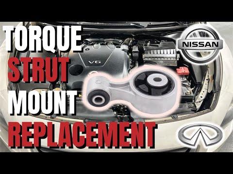
This procedure covers replacement of the right engine mount, left CVT mount, front torque rod, and rear torque rod. A torque rod is a lower mount that controls forward-and-back engine movement.
Assumption: Your Pathfinder retains its factory mounting hardware; AWD models have tighter access around the rear torque rod.
Difficulty Level: Advanced | Estimated Time: 5-8 hours
⚠️ Safety & Precautions
- ⚠️ Support the powertrain before loosening any mount. An unsupported engine can shift suddenly and cause serious injury.
- ⚠️ Never place any part of your body beneath a vehicle supported only by a floor jack.
- ⚠️ Lift the engine only by the approved lifting points or beneath the oil pan with a broad wood block. Never place a bare jack directly against the aluminum oil pan.
- ⚠️ Replace and tighten only one mount at a time. Removing several mounts can allow the engine and CVT to move out of position.
- ⚠️ Let the exhaust system cool completely before working near the rear torque rod.
- ⚠️ Disconnect the negative battery cable before removing the battery tray or working around the upper mounts.
- ⚠️ Do not start your Pathfinder while the engine or CVT is supported by a jack.
- ⚠️ Mount fastener specifications can vary by fastener location. Match every removed bolt to its original position.
🔧 Required Tools
You'll need the following tools for this repair:
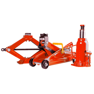
- 3-ton low-profile floor jack
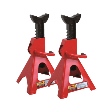
- 3-ton jack stands
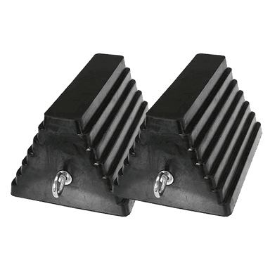
- Wheel chocks
- Engine support bar rated 1,000 lb minimum (specialty)
- 18-inch hardwood block
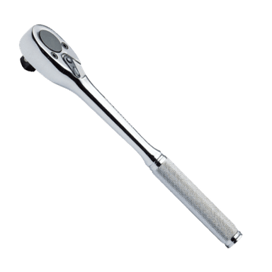
- 3/8-inch drive ratchet
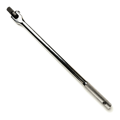
- 1/2-inch drive breaker bar
- 1/2-inch drive torque wrench rated 20-200 Nm
- 10mm socket
- 12mm socket
- 14mm socket
- 17mm socket
- 18mm socket
- 19mm socket
- 14mm combination wrench
- 17mm combination wrench
- 6-inch socket extension
- 12-inch socket extension
- Universal socket joint
- Flat-blade trim tool
- Small flat-blade screwdriver
- Paint marker
- Work light rated for automotive use
- Mechanic gloves
- Safety glasses
🔩 Required Parts
HowToo sells all the parts you need for this repair:
- Right engine mounting insulator - Qty: 1
- Left CVT mounting insulator - Qty: 1
- Front engine torque rod - Qty: 1
- Rear engine torque rod - Qty: 1
- Self-locking engine-mount nuts - Qty: As removed
- Single-use engine-mount bolts - Qty: As specified with replacement mounts
📋 Before You Begin
- 📋 Park your Pathfinder on firm, level ground. Select Park and apply the parking brake.
- 📋 Open the hood, switch the ignition off, and keep the intelligent key at least 10 feet away.
- 📋 Allow the engine and exhaust to cool completely.
- 📋 Photograph every mount and bracket before removal. Mark each bolt location with a paint marker.
- 📋 Loosen the negative battery-terminal nut with a 10mm socket. Disconnect and isolate the cable for at least three minutes.
- 📋 If using an engine support bar, attach it only to the factory engine lifting eyes. An engine support bar spans the fenders and holds the engine from above.
- 📋 If you cannot safely support the engine from above, replace only mounts reachable while supporting the powertrain from below with a floor jack and hardwood block.
🔨 Step-by-Step Instructions
Follow these steps in order:
Step 1: Raise and secure the vehicle
- Place the wheel chocks firmly behind both rear tires.
- Use the 3-ton floor jack at the front center jacking point, then place the 3-ton jack stands beneath the reinforced front side support points.
- Lower the vehicle onto the stands and gently push the body to confirm it is stable.
- Use a 10mm socket and flat-blade trim tool to remove the lower engine splash shield fasteners.
Step 2: Inspect and identify the failed mounts
- Use the work light to inspect each rubber insulator for splitting, separation, fluid leakage, or metal-to-metal contact.
- Use the paint marker to trace each mount and bracket position before loosening anything.
- Check for exhaust, hose, wiring, or axle contact that could be mistaken for a failed mount.
- Replace one mount before loosening the next.
Step 3: Support the engine and CVT
- Install the engine support bar across the reinforced body edges and connect it to the factory lifting eyes.
- Take up slack with the engine support bar only until it supports the engine. Do not lift the vehicle body.
- Alternatively, center the hardwood block on the 3-ton floor jack beneath the oil pan and apply only light upward pressure.
- Use the work light to watch nearby hoses, wiring, and exhaust parts while changing engine height.
Step 4: Replace the right engine mount
- Use a 10mm socket and small flat-blade screwdriver to remove the air-intake duct fasteners and release its clamps.
- Remove the duct and move attached hoses aside without stretching them.
- Use a 14mm or 17mm socket, as fitted, with the 6-inch extension to loosen the right mount-to-body fasteners.
- Use a 14mm or 17mm socket, as fitted, to remove the mount-to-engine-bracket fastener.
- Adjust the engine support bar or floor jack only a few millimeters until the fasteners slide out without binding.
- Remove the mount and compare its locating tabs and bolt spacing with the replacement part.
- Set the replacement mount into its original paint-marked position. Install every fastener by hand before tightening.
- Use the torque wrench to tighten the right mounting-insulator fasteners to 55 Nm (41 ft-lbs), unless the replacement fastener instructions specify otherwise.
- Use a 10mm socket to reinstall the intake duct fasteners until snug; do not crush the plastic.
Step 5: Replace the left CVT mount
- Use a 10mm socket to loosen the battery-terminal clamps and battery hold-down fasteners.
- Lift the battery straight out while wearing mechanic gloves. Keep it upright.
- Use a 10mm and 12mm socket with the 6-inch extension to remove the battery tray and attached harness retainers.
- Support the CVT with the floor jack and hardwood block. Apply only enough pressure to carry its weight.
- Use a 14mm or 17mm socket, as fitted, with the extensions to remove the left mount-to-body fasteners.
- Use a 14mm or 17mm socket, as fitted, to remove the left mount-to-CVT bracket fastener.
- Adjust the jack slightly until the old mount lifts out without prying against the CVT case.
- Position the replacement mount using the original locating tabs and paint marks. Start every fastener by hand.
- Use the torque wrench to tighten the left mounting-insulator fasteners to 55 Nm (41 ft-lbs), unless the replacement fastener instructions specify otherwise.
- Use a 10mm and 12mm socket to reinstall the battery tray and harness retainers securely.
- Leave the battery disconnected until all mounts are installed.
Step 6: Replace the front torque rod
- Confirm the engine remains supported by the engine support bar or floor jack and hardwood block.
- Use a 17mm or 18mm socket, as fitted, with the breaker bar to loosen the front torque-rod through-bolts.
- Adjust engine height slightly if either bolt binds. Never drive a bolt out while the mount is heavily loaded.
- Remove the old torque rod and install the replacement in the same direction.
- Insert both bolts by hand and lower the powertrain to its natural resting position before final tightening.
- Use the torque wrench to tighten both front torque-rod fasteners to 103 Nm (76 ft-lbs).
Step 7: Replace the rear torque rod
- Use the work light to locate the rear torque rod between the powertrain and rear crossmember.
- On AWD models, use the universal socket joint and 12-inch extension to work around the transfer assembly and exhaust. Do not pry against either component.
- Use a 17mm or 18mm socket, as fitted, with the breaker bar to loosen the rear torque-rod fasteners.
- Adjust the engine support slightly until the bolts can be removed by hand.
- Match the replacement rod's orientation to the original and install both bolts finger-tight.
- Return the engine to its neutral resting position.
- Use the torque wrench to tighten both rear torque-rod fasteners to 103 Nm (76 ft-lbs).
- If access requires loosening the front suspension member or exhaust, stop and use the Nissan service procedure; those components require additional support and alignment controls.
Step 8: Settle the powertrain and verify clearances
- Slowly release the engine support bar or lower the floor jack while watching all four mounts with the work light.
- Confirm every locating tab is seated and no wiring, hose, heat shield, or exhaust component is trapped.
- Use the torque wrench to recheck every accessible mount fastener at its specified torque.
- Use the paint marker to place a witness mark across each tightened fastener and bracket.
Step 9: Reassemble the vehicle
- Use a 10mm socket to reinstall the battery hold-down and tighten it until the battery cannot move. Do not overtighten the battery case.
- Connect the positive battery terminal first, followed by the negative terminal.
- Use the 10mm socket to tighten each terminal to 5.4 Nm (48 in-lbs).
- Use the flat-blade trim tool and 10mm socket to reinstall the lower splash shield.
- Use the 3-ton floor jack to raise the vehicle, remove the jack stands, and lower your Pathfinder fully.
✅ After Repair
- ✅ With the hood open, hold the brake firmly and start the engine. Listen for knocking and watch for excessive engine movement.
- ✅ Keep the brake applied and shift slowly through Reverse, Neutral, and Drive. Pause for three seconds in each position.
- ✅ Stop immediately if the engine jumps sharply, a mount shifts, or metal contacts the body.
- ✅ Reset the clock and automatic window function if they were lost during battery disconnection.
- ✅ Road-test at low speed first. Check for vibration during idle, acceleration, deceleration, and reverse engagement.
- ✅ Reinspect all mounts and paint marks after 25-50 miles. No fastener should have moved.
- ✅ If vibration is worse, check for a preloaded mount, trapped exhaust component, or mount installed in the wrong orientation.
💰 DIY vs Shop Cost
Shop Cost: ₹70,000-₹145,000 (parts + labor)
DIY Cost: ₹28,000-₹75,000 (parts only)
You Save: ₹42,000-₹70,000 by doing it yourself!
Labor around Sonīpat varies by workshop and imported-parts availability. This repair takes a shop approximately 5-8 hours.
🎯 Ready to get started?
HowToo makes it easy: same-day/2-day shipping on every part, plus all the tools and specialty tools you need! Check out the parts and tools sections below to add everything to your cart.