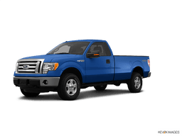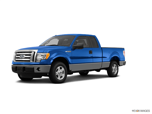

How to Replace Engine Mounts on a 2011-2016 Ford F-150 3.7L 4WD (Engine: V8 5.0L)
Step-by-step instructions with required tools, parts, torque specs, and safety tips for 2011, 2012, 2013, 2015, 2016
How to Replace Engine Mounts on a 2011-2016 Ford F-150 3.7L 4WD (Engine: V8 5.0L)
Step-by-step instructions with required tools, parts, torque specs, and safety tips for 2011, 2012, 2013, 2015, 2016


🔧 F-150 - Engine Mount Replacement
Assumption: This procedure replaces both hydraulic engine-mount insulators on a stock 4WD F-150.
The left and right engine mounts secure the engine to the front crossmember and absorb vibration. Replacement requires supporting and carefully raising the engine; limited clearance around the front differential makes this an advanced repair.
Difficulty Level: Advanced | Estimated Time: 5-8 hours
⚠️ Safety & Precautions
- ⚠️ Never work beneath an engine supported only by a floor jack.
- ⚠️ Use an engine support bar across the strut towers before removing mount fasteners.
- ⚠️ Do not place a jack directly against the aluminum oil pan.
- ⚠️ Raise the engine only enough to unload the mounts. Excess movement can damage hoses, wiring, the fan, exhaust, or transmission mount.
- ⚠️ Support the front differential with a transmission jack if it must be lowered for clearance.
- ⚠️ Replace one engine mount at a time so the engine remains controlled.
- ⚠️ Disconnect the negative battery cable before moving the engine.
- ⚠️ Allow the engine and exhaust system to cool completely.
🔧 Required Tools
You'll need the following tools for this repair:
- Engine support bar rated 1,000 pounds minimum (specialty)
- Transmission jack rated 1,000 pounds minimum (specialty)
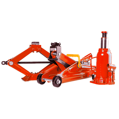
- Floor jack rated 3-ton minimum
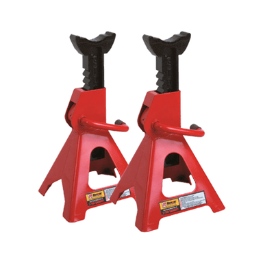
- Jack stands rated 3-ton minimum
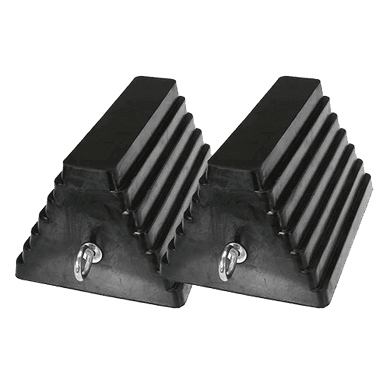
- Wheel chocks
- 8mm socket
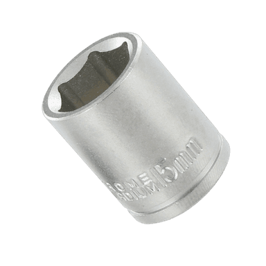
- 10mm socket
- 13mm socket
- 15mm socket
- 18mm deep socket
- 21mm socket
- 8mm ratcheting wrench
- 13mm combination wrench
- 15mm combination wrench
- 18mm combination wrench
- 3/8-inch-drive ratchet
- 1/2-inch-drive ratchet
- 1/2-inch-drive breaker bar
- 3/8-inch-drive 6-inch extension
- 1/2-inch-drive 10-inch extension
- 3/8-inch-drive universal joint
- 1/2-inch-drive universal joint
- Torque wrench rated 10-100 Nm
- Torque wrench rated 40-200 Nm
- Trim-clip removal tool
- Flat-blade screwdriver
- Paint marker
- Work light
- Mechanic’s gloves
- Safety glasses
🔩 Required Parts
HowToo sells all the parts you need for this repair:
- Left engine-mount insulator - Qty: 1
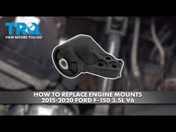
- Right engine-mount insulator - Qty: 1
- Engine-mount retaining hardware - Qty: 1 set
- Front differential mounting hardware - Qty: 1 set if removed
Replace the left and right mounts as a pair. Use mounts specifically cataloged for the 3.7L engine and 4WD chassis.
📋 Before You Begin
- Park your F-150 on level, solid ground. Shift to Park, apply the parking brake, and chock both rear wheels.
- Open the hood and allow the engine to become completely cold.
- Record any radio presets you want to keep.
- Inspect the replacement mounts before disassembly. Left and right mounts are different and must not be interchanged.
- Because 4WD front-differential clearance varies with production configuration, compare access around both mounts before lowering the differential.
- An engine support bar spans the engine bay and holds the engine from above. Install it exactly as directed by its manufacturer.
🔨 Step-by-Step Instructions
Follow these steps in order:
Step 1: Disconnect the Battery
- Use an 8mm socket and 3/8-inch-drive ratchet to loosen the negative battery-terminal clamp.
- Lift the cable from the terminal and position it where it cannot spring back.
Step 2: Create Upper Engine Clearance
- Use an 8mm socket or flat-blade screwdriver to loosen the air-intake tube clamps.
- Disconnect the airflow-sensor electrical connector by releasing its locking tab by hand.
- Remove the intake tube and upper air-cleaner housing. Cover the exposed throttle-body opening with a clean cover.
- Check the radiator fan and shroud clearance. Remove the upper shroud fasteners with an 8mm or 10mm socket if raising the engine could make the fan contact the shroud.
- Use a paint marker to mark the shroud’s installed position.
Step 3: Raise and Secure the Truck
- Use the 3-ton floor jack at the specified front frame lifting point.
- Place 3-ton jack stands beneath both front frame rails, then lower the truck onto them.
- Gently push the truck to confirm that it is stable before going underneath.
- Use a 13mm or 15mm socket and ratchet to remove the front splash shield, depending on the installed fasteners.
Step 4: Install the Engine Support Bar
- Position the 1,000-pound engine support bar across structurally reinforced body locations according to the support-bar instructions.
- Attach its chain to approved engine lifting eyes. A lifting eye is the reinforced metal loop intended to support the engine.
- Tighten the support-bar screw by hand until the chain is taut. Do not lift the truck or pull the engine upward yet.
Step 5: Inspect Components That Could Bind
- Use the work light to inspect radiator hoses, heater hoses, wiring harnesses, fuel lines, air-conditioning lines, exhaust connections, and the transmission-mount area.
- Release any tight wiring retainers with the trim-clip removal tool.
- Do not disconnect refrigerant lines or open the fuel system.
- Photograph every bracket before removing it.
Step 6: Remove the Mount-to-Crossmember Nuts
- Locate the lower stud and nut for each engine mount where it passes through the crossmember.
- Use an 18mm deep socket, extension, universal joint, and 1/2-inch-drive breaker bar to loosen the mount nuts.
- Remove both nuts with the 18mm deep socket and ratchet, but continue replacing only one mount at a time.
Step 7: Check Front Differential Clearance
- Use the work light to determine whether either mount can leave the chassis without contacting the 4WD front differential.
- If clearance is sufficient, leave the differential installed and continue to Step 9.
- If clearance is insufficient, proceed to Step 8. Do not force the mount past the differential, axle housing, or oil pan.
Step 8: Lower the Front Differential Slightly if Required
- Center the 1,000-pound transmission jack beneath the front differential housing and apply light supporting pressure.
- Use the paint marker to mark the differential supports and brackets in their installed positions.
- Use 18mm and 21mm sockets with the breaker bar to loosen the differential mounting fasteners. Do not disconnect axle shafts, driveshafts, vent hoses, or electrical wiring.
- Remove only the fasteners necessary to lower the differential enough for mount clearance.
- Slowly lower the transmission jack while watching the axle seals, vent hose, driveshaft, and wiring. Stop immediately if anything becomes tight.
- Keep the differential fully supported by the transmission jack.
Step 9: Raise the Engine Slightly
- Turn the engine support-bar screw slowly to raise the engine approximately 10-15mm.
- Watch the fan, shroud, hoses, wiring, exhaust, transmission mount, and oil pan continuously.
- Stop when the mount studs clear the crossmember. Do not lift farther than required.
Step 10: Remove the First Engine Mount
- Choose the mount with the best access first.
- Use a 13mm or 15mm socket, extension, universal joint, and ratchet to remove its engine-side retaining bolts.
- Support the mount by hand as the final bolt is removed.
- Guide the mount out without prying against the oil pan, steering components, or differential.
- Compare the old and new mount. Confirm matching stud location, bracket angle, heat shielding, and locating tabs.
Step 11: Install the First New Mount
- Place the correct new mount in its original orientation.
- Start every engine-side bolt by hand for at least three full turns. This prevents cross-threading.
- Use the appropriate 13mm or 15mm socket to snug the bolts evenly.
- Do not fully tighten the mount while its locating stud is out of the crossmember opening.
- Use the engine support bar to lower the engine slightly and guide the mount stud into the crossmember by hand.
- Install the lower nut by hand but leave it loose.
Step 12: Replace the Second Engine Mount
- Use the engine support bar to unload the remaining mount.
- Use the appropriate 13mm or 15mm socket, extension, universal joint, and ratchet to remove its engine-side bolts.
- Remove the old mount and install the correct replacement in the same orientation.
- Start all fasteners by hand, then guide the lower stud into the crossmember.
- Install the second lower nut by hand.
Step 13: Align and Tighten the Engine Mounts
- Lower the engine gradually with the support bar until its full weight rests naturally on both mounts.
- Check that both locating features are seated and neither mount is twisted or trapped against another component.
- Use a torque wrench and the appropriate 13mm or 15mm socket to tighten the engine-side mount bolts to Torque to 48 Nm (35 ft-lbs).
- Use a torque wrench and 18mm deep socket to tighten both mount-to-crossmember nuts to Torque to 85 Nm (63 ft-lbs).
- If replacement hardware provides a different torque specification, follow the hardware manufacturer’s specification.
Step 14: Reinstall the Front Differential if Lowered
- Use the transmission jack to raise the differential until the paint marks align and all bolt holes are centered.
- Start every differential fastener by hand before tightening any one fastener.
- Use 18mm and 21mm sockets to snug the fasteners evenly.
- Because front-differential fastener torque depends on the exact mounting position and fastener type, verify the matching Ford service specification before final tightening. Do not estimate this torque.
- Remove the transmission jack only after every differential fastener is correctly tightened.
Step 15: Remove the Support Equipment
- Release tension from the engine support bar slowly while watching both mounts.
- Confirm that the engine remains centered and both mount studs stay seated.
- Disconnect and remove the engine support bar.
Step 16: Reassemble the Engine Bay
- Reinstall any radiator-shroud fasteners with the appropriate 8mm or 10mm socket.
- Reinstall the air-cleaner housing and intake tube.
- Use the 8mm socket or flat-blade screwdriver to tighten the intake clamps until secure without crushing the plastic tube.
- Reconnect the airflow-sensor connector until its lock clicks.
- Use a 13mm or 15mm socket to reinstall the splash shield.
Step 17: Lower the Truck and Reconnect the Battery
- Use the 3-ton floor jack to raise the frame slightly, remove both jack stands, and lower the truck completely.
- Install the negative battery cable.
- Use the 8mm socket and torque wrench to tighten the battery-terminal clamp to Torque to 5 Nm (44 in-lbs).
✅ After Repair
- ✅ Before starting, inspect the fan, intake tube, wiring, hoses, front differential, and all removed fasteners.
- Start the engine with the transmission in Park and let it idle. Keep hands and tools away from rotating components.
- Listen for knocking and check for excessive vibration. Shut the engine off immediately if the fan contacts the shroud or the engine moves abnormally.
- With the brake pedal firmly applied, shift slowly through Reverse, Neutral, and Drive. A helper should watch for abnormal engine movement from a safe position beside the truck.
- Take a short, low-speed road test. Recheck for vibration, clunks, loose shields, leaks, and differential noise afterward.
- If the front differential was lowered, inspect its axle seals and mounting points again after the road test.
- No battery registration, scan-tool programming, EPB service mode, or infotainment procedure is required for this repair.
💰 DIY vs Shop Cost
Shop Cost: ₹55,000-₹95,000 (parts + labor)
DIY Cost: ₹18,000-₹38,000 (parts only)
You Save: ₹37,000-₹57,000 by doing it yourself!
Local labor and imported-parts pricing vary. This repair takes a shop approximately 5-7 hours, with additional time possible if the front differential must be lowered.
🎯 Ready to get started?
HowToo makes it easy: same-day/2-day shipping on every part, plus all the tools and specialty tools you need! Check out the parts and tools sections below to add everything to your cart.